• This forum is the machine-generated translation of www.cad3d.it/forum1 - the Italian design community. Several terms are not translated correctly.

question about the correctness of the mass at table of solid 3d

  • Thread starter Thread starter dotickima
  • Start date Start date

dotickima

Guest
Good evening.

I am a three-year student of the degree program of industrial automation and I created this thread to ask you a verification on the realization of the views and technological quotas inserted in the drawing.

I am following a course called "virtual prototyping" in which we study and learn the foundations of prototyping using catia v5 software.

I would point out that in the previous years we have never had specific courses on mechanics (if not a course on the fundamentals of mechanics) and I realize that I have gaps to fill, so the more errors you will underline better will be for me.

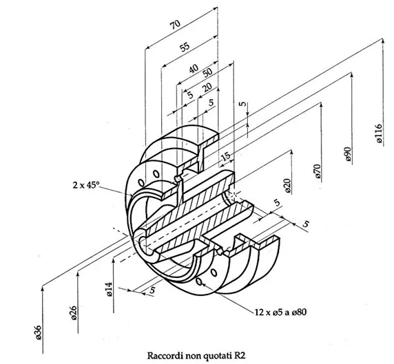
the purpose of the exercise that I have to carry out is to realize in 3d the solid represented in fig.1, then I must realize the table of the solid and finally the technological quotation. for the moment tolerance must be neglected as it will be the subject of the next lessons.

In fig.1 there is the design of the exercise, in fig.2 the solid 3d is reported while in fig.3 the table is represented with the addition of the technological quotas.

the view in fig.3 is correct? Are technological quotas correct? If not, for what reasons?

Good evening.
 

Attachments

  • solido1.webp
    solido1.webp
    28 KB · Views: 18
  • solido2.webp
    solido2.webp
    35.4 KB · Views: 22
  • solido3.webp
    solido3.webp
    38.8 KB · Views: 29
Hi.
before you can help yourself, what do you mean in a big word for technological quotas?
 
5 thicknesses on the right I would systematically replace them with diameters that you can also measure for control.

the 5 x12 hole quotation I find it bizarre.
I know what you mean but you don't convince me.
 
you should mainly understand how to produce it.
so much to understand the 5 thicknesses could make sense if you merge it, but do not have it if you do it as a tool machine.
this only to make you understand that listing is not as trivial as it seems and there must be, when you will make productive drawings and not exercises, reasoning at the base.
returning to your design we take it for what is an exercise and as such we examine it:
-as clarified by falonef are the internal diameters and not the thicknesses, both for proper measurement and because the possibility that a thickness is functional is almost nothing
- The bevel is not listed like that: it puts the width and the portion of the corner or puts a linear quota with width + angle
- drilling does not quote like that: put the hole axis and with that quoti the drilling diameter (80?) also indicate that the holes are equidistant
-you should not ask the operator to make calculations so the end angle should be placed in the attic, if it is not functional or if it is not a precise angle you can put it in brackets
- the quotas on the right must be revised because put with little logic

read this dispensationwww.fataing.poliba.it/admin/gestione_documenti/.../1318827128mod7-quotature.pdf
 
for the bevel I agree that you do not quote so or at least I learned at the time that you do not quote(va) so.

then I take care of giving classes catia v5 and actually ds has just implemented this function with various options.
every time I show you during the courses there was never an objection from the participants.
Now the question I ask myself is:
If this is not quoted, why did ds split into two to make it available in catia v5?!? !

are we sure that does not correspond to some (new) norm?
 
Perhaps in some non-mechanical field there is the need, as a rule, to quote a inclination in that way. I know, a facade of a building in architecture. . .
beyond the norms that quota, which however is not interpretable and does its dirty informative work, subtracts a lot of space to the area of the design, so also worth a little ' the eye blow and good sense/experience; the rules indicate that quotas must be crossed as little as possible
 
But here's what ds in catia v5 offers.
the fact is that from us the standard office, which must validate the drawings, has never objected to the use of this type of quota.
and say that our office standards is quite "rigid".
 

Attachments

  • fase-tools.webp
    fase-tools.webp
    15.7 KB · Views: 11
also in solidworks there is that type do quota, with the possibility to straighten the text, which among other uses with ease.
I don't know what to say. maybe, being software that meet the requirements of various international standards, that method is valid for the Asian or American market.... hypotheses
Probably so.

I would like to know what you mean by technological quotas?
in catia v5 there is this toolbar but I never understood what it is for.
@massivonweizen: Does it also exist in solidworks? If you know what it's for?
 

Attachments

  • tf.webp
    tf.webp
    4.3 KB · Views: 3
Good morning, thanks for the quick dock answers.
What do you mean by technological odds?
with technological quotas I mean the necessary quotas in order to physically realize the piece indicated.

I modified the odds trying to follow the suggestions and imagining all mechanical steps from a cylindrical piece assuming that the piece is made for removal of truciole using a lathe and a milling.

the final quotation I obtained is in fig 1.

I currently have the following doubts:
- how can I insert the hole quotation without overlapping the existing quotas? Should I reposition the quotas?
- assuming that the tilted part is produced after creating the upper whole pocket, how can I insert the angle without accavallating it on the other odds?

the only solution I thought about is to insert a view from above so as to move some odds on this new view.

Finally, there is a command to make parallels of the already inserted quotas?
 

Attachments

  • solido3.webp
    solido3.webp
    37.3 KB · Views: 7
Maybe it matches the dimexpert odds.
I'll take you back http://help.solidworks.com/2016/italian/solidworks/sldworks/c_dimxpert_for_parts.htmis an advanced tool to combine theory and practice, said in pennies. from what I know are read also from the cam making the paper design pure formality
solid scratches,
but the toolbar I posted I find it in catia v5 working environment drafting (drawing) then pure 2d.

nothing to do with 3d shares with 3d philosophy.master. This is all another story:-)
 
we have online help.
but I don't understand what that bar is useful because there's already an almost idebtic
you wrote that But I never understood what it takes.
It is possible to create quotas for technological features such as electrical wiring or between technological features such as structural plates.
 
in fact and I confirm.
what are the structural plates and what is the advantage of using that toolbar and not the one so to say standard?

If you know, can you give me a good example? Thank you.
 

Forum statistics

Threads
44,997
Messages
339,767
Members
4
Latest member
ibt

Members online

No members online now.
Back
Top