• This forum is the machine-generated translation of www.cad3d.it/forum1 - the Italian design community. Several terms are not translated correctly.

questions about geometric tolerances

  • Thread starter Thread starter Martakynghi
  • Start date Start date

Martakynghi

Guest
Hello I was doing this exercise but I wanted to have confirmation from you.
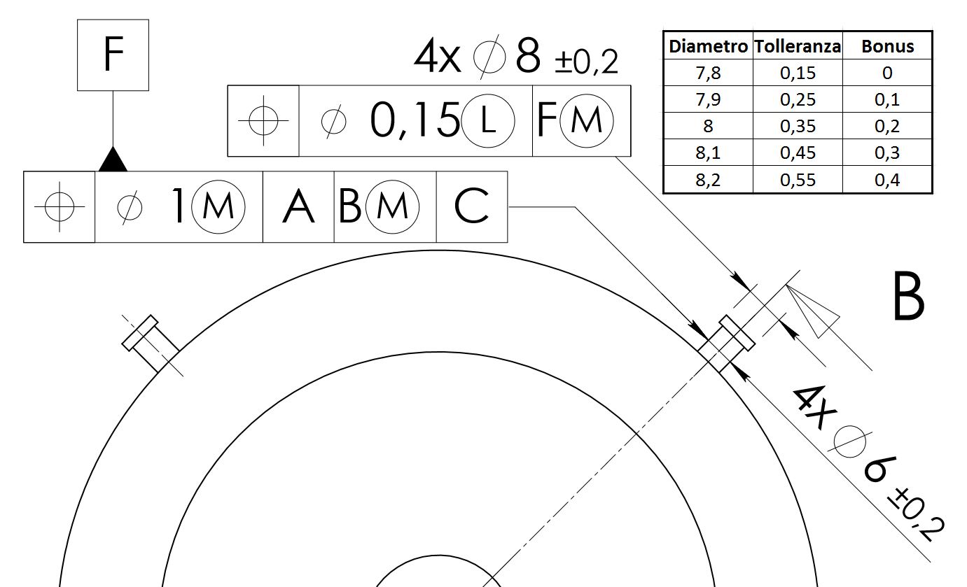
I would have written that the geometric property that is controlled is straight and is not an associate tolerance. the geometric element is the axis of symmetry. the tolerance zone is limited by a plane between two cylinders whose difference is 0.04 in diameter. In this case it is possible to increase the tolerance value of a value equal to the difference between the actual size and maximum material and it is possible from the application of the modifier of maximum material.
 

Attachments

  • IMG_20200104_160841.webp
    IMG_20200104_160841.webp
    292.7 KB · Views: 35
for the tol_2 the geometric property that is controlled is the inclination and is an associate tolerance. the geometric element to which tolerance is applied is a plane . the tolerance zone is referred to a sloped plane compared to a reference plane forming an exact angle different from 0 and 90°
 
for the tol_2 the geometric property that is controlled is the inclination and is an associate tolerance. the geometric element to which tolerance is applied is a plane . the tolerance zone is referred to a sloped plane compared to a reference plane forming an exact angle different from 0 and 90°
and its tolerance value 0.4?Screenshot_20200104_185130.webp
 
Moreover the 40th is a ted therefore exact value of angle, if ever parallel for the tolerance of geometry of 0.4....but 40,00000000° must be ??
 
I'd like to know if I'm doing this exercise well.
I have doubts about the modifier of maximum material.

for the tol_1
the geometric property that is controlled is the location and is an associate tolerance.
the geometric element to which tolerance is applied is the axis of symmetry.
the tolerance zone is referred to the surface a, since in the geometrical tolerance pane it is indicated with the symbol (m) the application of the maximum material condition then the actual deviant size from the value of 20.5 and this deviation increases the width of the geometric tolerance zone.
for the tol_2
geometric property is straightness.
the geometric element is the axis of symmetry.
the tolerance zone is limited by a cylinder diameter t and the cylinder axis must be included in a cylindrical zone with a diameter of 0.08 mm.
since the geometric tolerance pane is not indicated the symbol of the modifier of maximum material we can deduce that it is not applied.
 

Attachments

  • IMG_20200109_133850.webp
    IMG_20200109_133850.webp
    199.4 KB · Views: 14
Do you guys help me understand Part 2 3?
for the tol_1 we have a tolerance of parallelism therefore the tolerance zone is limited by two parallel planes distant 0.1 mm and parallel to the reference surface f. then the mmc can be applied? because it can be applied to a fos whose size is controlled by a dimensional tolerance. . Okay?
 

Attachments

  • IMG-20200114-WA0020.webp
    IMG-20200114-WA0020.webp
    102.8 KB · Views: 16
boys good morning and hopefully finish quickly is situation. . work in precision mechanics but are a little rusty.. in particular on max/min material tolls. I have looked at all the open discussions in this matter and I think I have understood the concept. But below I would ask you to clarify the matter on an exercise that aims to ensure the min thickness of the edge (I mean it as a diametric "delta" between the head and rivet stem). any of you kindly can comment on the tolerances indicated in the figure below, in particular to what the values of 0.15 and 1 ? thanks

the last example concerns a plastic component, whose functional requirement is the minimum thickness of the 4 radial connecting pins (Figure 4). with the use of the minimum material modifier you can protect the minimum thickness of the edge in all conditions (figure 5).
Figure 4. quotation of a plastic component, whose functional requirement is the minimum thickness of the 4 radial connecting pins. Figure 5. with the use of the minimum material modifier (and the maximum material on the reference) you can protect the minimum thickness (0,725 mm) of the edge in all conditions.
in fact, to the maximum material:
to the mini material:
 

Forum statistics

Threads
44,997
Messages
339,767
Members
4
Latest member
ibt

Members online

No members online now.
Back
Top