• This forum is the machine-generated translation of www.cad3d.it/forum1 - the Italian design community. Several terms are not translated correctly.

rectangular tubes

  • Thread starter Thread starter MB_MAN
  • Start date Start date

MB_MAN

Guest
hi to all, I wanted to start creating tubes, but all about the rectangular tubes with inventor in the sheet section and then have the development of the sheet to pass the drawing to the laser cutting machine, but I can't understand how to create these tubes.

Can any of you help me?? use inventor 2013 ita
 
So your pipe is not closed on all sides right? However you could proceed in several ways, the first that comes to mind is creates sketch, drawing the section of your tube including light on the broken side, then flange of contour.
 
So your pipe is not closed on all sides right? However you could proceed in several ways, the first that comes to mind is creates sketch, drawing the section of your tube including light on the broken side, then flange of contour.
no pipe is closed.

I have not understood how to do you know, apparatuses that have just worked in this environment and I do not know all the functions and methods to use inventor.

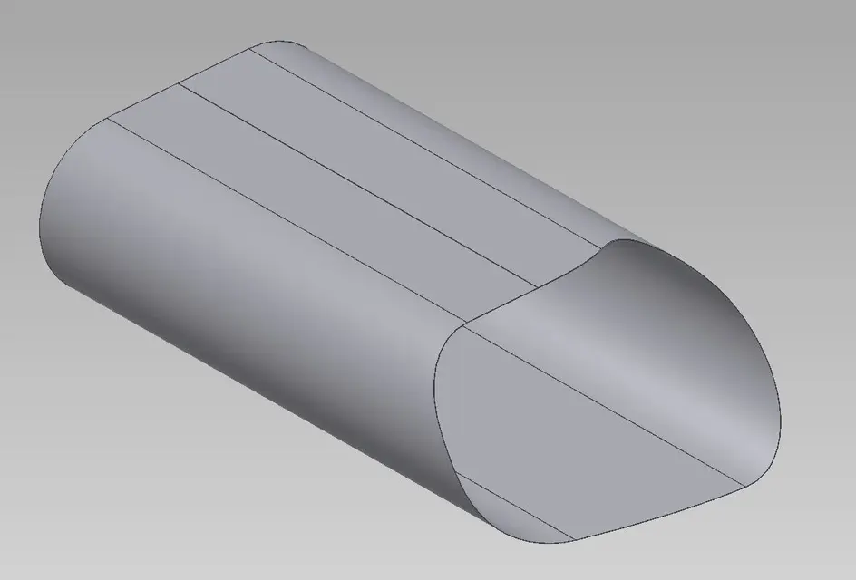
Could you explain it better how to create a hose even oval not by force of retangular things with inventor and then have development? ?

my tube must be 50mm height and ø50mm external diameter with a 2mm thick sheet. I would like to develop something like this for inventor
 
no pipe is closed.

I have not understood how to do you know, apparatuses that have just worked in this environment and I do not know all the functions and methods to use inventor.

Could you explain it better how to create a hose even oval not by force of retangular things with inventor and then have development? ?

my tube must be 50mm height and ø50mm external diameter with a 2mm thick sheet. I would like to develop something like this for inventor
a closed profile cannot be developed by inventor.
as in reality.
If you have a tube and you want to "stain" you have to open it.
If you have a sheet and the calandri, to have a pipe, you will have to weld it, but you still have a rolled sheet.
However, apart from these philosophical dissertations,
Designed in sheet metal environment, the profile sketch of your pipe, then open it, which creates a profile break. (even 1 cent of mm can go well).
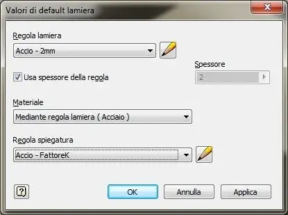
in the "default sheet values" window sets the thickness you need
If it's a round or oval tube (actually if you get it by rolling) put the k=0,5 factor otherwise leave the k factor you find.
then use the "flangia contour" command and give it the height you want.
at this point you can use the "flat model" command and you will have your development.:smile:
p.s.
It is called rectangular, not retangular. .
 
I think I understand that mb_man must cut a tube with the lasertube, but some more dated systems do not have a cam 3d, so by not importing directly the step, they need a flat development like it was an open sheet, then the laser program fits the tube, I understand well?
time ago our former supplier had asked me something similar on a tube full of grooves and it seems to have worked, now fortunately they have all the "modern" cam and just the steps!

to make development just draw the tubular as a normal tube, then cut a few tenths in the long part, convert it into sheet metal, check the correct material and develop it.
if you need it for the reason written above, I recommend you not to use a thickness of 2mm, otherwise then the grooves would not be real, I recommend you to make ø out 50 thickness 0.2mm.

attach the images of an example, find the 3d of the finished piece with sp3mm, then the 3d of the tube adapted with reduced thickness and cutting, finally the development in the plane
 

Attachments

  • Finito.webp
    Finito.webp
    19.2 KB · Views: 8
  • 3d_Sviluppo.webp
    3d_Sviluppo.webp
    20.9 KB · Views: 7
  • Sviluppo.webp
    Sviluppo.webp
    23.8 KB · Views: 7
I think I understand that mb_man must cut a tube with the lasertube, but some more dated systems do not have a cam 3d, so by not importing directly the step, they need a flat development like it was an open sheet, then the laser program fits the tube, I understand well?
time ago our former supplier had asked me something similar on a tube full of grooves and it seems to have worked, now fortunately they have all the "modern" cam and just the steps!

to make development just draw the tubular as a normal tube, then cut a few tenths in the long part, convert it into sheet metal, check the correct material and develop it.
if you need it for the reason written above, I recommend you not to use a thickness of 2mm, otherwise then the grooves would not be real, I recommend you to make ø out 50 thickness 0.2mm.

attach the images of an example, find the 3d of the finished piece with sp3mm, then the 3d of the tube adapted with reduced thickness and cutting, finally the development in the plane
I think you got my problem.... .
 
I think I understand that mb_man must cut a tube with the lasertube, but some more dated systems do not have a cam 3d, so by not importing directly the step, they need a flat development like it was an open sheet, then the laser program fits the tube, I understand well?
time ago our former supplier had asked me something similar on a tube full of grooves and it seems to have worked, now fortunately they have all the "modern" cam and just the steps!

to make development just draw the tubular as a normal tube, then cut a few tenths in the long part, convert it into sheet metal, check the correct material and develop it.
if you need it for the reason written above, I recommend you not to use a thickness of 2mm, otherwise then the grooves would not be real, I recommend you to make ø out 50 thickness 0.2mm.

attach the images of an example, find the 3d of the finished piece with sp3mm, then the 3d of the tube adapted with reduced thickness and cutting, finally the development in the plane
Okay.
However, the development process is the same.
The only thing to keep in mind, as you say, is to develop a solid as thinner to approach the outer surface of the piece. .
 
how do I change the "sheet defult values" on inventor 2013,

ie every time I go to open meeting inventor always as thickness 0.50mm, while I would like these as defult values when I start inventor.
 

Attachments

  • accio.webp
    accio.webp
    13.6 KB · Views: 19
  • accio 2.webp
    accio 2.webp
    33.8 KB · Views: 7
  • accio 3.webp
    accio 3.webp
    37.3 KB · Views: 6

Forum statistics

Threads
44,997
Messages
339,767
Members
4
Latest member
ibt

Members online

No members online now.
Back
Top