• This forum is the machine-generated translation of www.cad3d.it/forum1 - the Italian design community. Several terms are not translated correctly.

reference and associative lines

  • Thread starter Thread starter aerox
  • Start date Start date

aerox

Guest
hello to everyone, I'm finally succeeding in doing something with this program, only though I clashed with a problem not recently.
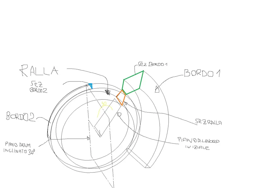
I build for extrusion of revolution a ralla (type a ring with a parallel surface to yz and an inclination always compared to yz. now I want to add a board for 90 degrees outside the ring, made by a parallel profile: if I support the work plan that generated the first extrusion I can get some construction lines using the "curve on edge" command (or even directly snap on the tops that interest me) and then if the original geometry changes, this edge follows the geometry on which it is built

Now, if instead I use a tilted working plan type of 30 degrees (and always passing through the axis of revolution), it is impossible to take the lines of the generated solid, to the most I can take those of the previous section only that they are projected and I do nothing.

provisionally I decided to "reconstruct" the original profile (which generated the first extrusion of the ring) with a construction line and on this build the parallelgram that generates me the edge (always in extrusion for revolution).

Of course, if the ring geometry varies, the edge does not follow geometry because I have no association.

I know a little proe and there in the sketch environment it is possible to recover the lines or with the command on purpose "line from edge" or inserting the lines that interest as references, it seems impossible here you can not do something similar, so you are my only hope... I remain 4 days to fix this thing, I hope well to succeed somehow...

thanks to all

Hi.
 
Of course, in words, I'm not much to explain, maybe so you understand right away.

summing up: on the initial work plane design a section (red) from which for extrusion I draw a ring. I then want to add a border with a section (green) : in this case I am on the red section plane and then I can use geometry as a reference and therefore there is association.
I then create a 30 degree sloping plan, imposed on this the work plan, and then "I try" to draw a section (blue) that I would have the base referenced to the extruded ring, unfortunately I can not catch the lines generated with the extrusion, I can take the lines of the red or green sez (which are projected with the line command on edge) but I do nothing.

Hi.
 

Attachments

  • ralla.webp
    ralla.webp
    47.5 KB · Views: 23
So... here, there's a choice of the most effective and/or the most appreciated. said this, in my opinion the procedure is this, once made the two profiles on the working plane (in the first red profile I recommend to make the axis of revolution with creates reference and with the ground on an extreme), put the plan with button dx working plan here, on the face of the solid or appendix created by the green profile. do this right-click on the red axes with lock, move the axes to the top of the rotation axle, then again right-click on the always red axes and rotates 30°. Now you can do the blue profile, and you can put the parallel odds from the initial rotation axis (I think, now I don't have think3). you can also try to draw a reference line (like a line equal to the circle radius) on the first and third profile, and put a quota that will be 30°. changing the quota to e.g. 25° you should update (maybe:confused::confused:). I hope to be explained, we are affected by any clarification:finger:
 
Meanwhile thanks for the information, unfortunately I have a mentality derived from proes (which was my first approach to modeling 3d) and it seems very ostico think.

In general when I build anything on profile 2d I always put two orthogonal axes on ground as a reference to be able to use them after to put holes and do other things.

If I understand well what you tell me is a way to avoid drawing on a datum plan but to use the reference system to place me as a right serve?

I could use a reference line (would it be the classic line of construction?) and draw the new profile, but if then change the radius of the ring, I would have the appendix not changed. or did I misunderstand what you explained?
I mean, if the model remains such and what I can do what I need, but in case there are variations, the appendixes do not change
if you can place the e3 file (version 2009.3) that you may understand even better

Thank you
Hi.
In fact, I never liked to lean on the datum planes, however if you need to "move" the diameter of the piece you do differently, try to create an initial profile on the xy plane made of only reference lines (in the profile environment those section point), consisting of a circle and two rays, then put the altitude 30° between the rays and constraints to duty. made this button dx on a radius, worktop here, align x to the radius positions the aars to the end of the ray and roar the aars as you need to make the first profile (always with red axes with lock). same procedure for the third profile, which of course you will have to support the second ray. If the first "base" profile is properly bound, for each radius value you will have what you want:finger:
 
Okay! I think I understand what you want to explain to me, in practice I would do this, tell me if I understood right:

design on a profile 2d a circle (e.g. max external ring footprint), a radius on which to place the first profile and the second tilted radius of 30grades for the second profile (all with construction line

this profile 2d do not use it to make any solid
I support one of the two rays with the work plan 8allineando axis x and from there start new profile that then generates me the solid extrusion
If I redefine the initial circle the profiles will also move because they are connected :-)

Now after the words I try!
Thank you very much
 
then it is just as you suggested, in this way I can keep the ring associated and the appendix, the only drawback is that to change the geometry you must in part put hand to the basic 2d profile (circle+2 rays) and on the 2d profile that generates the ring.

then with a datum point I managed to give association to the base of the appendix!

I would say that it is not so immediate to work in 3d with this program, it seems much faster proe and sw!

one last question: I have not yet understood what difference is when there is the red luchetto on the origin of the reference system, or a celestial square. I really don't get this back.

Hi.
 
So... make me order, to change the diameter in any case you have to change the quota, or the profile of revolution or the "base" profile. However I did not understand whether the basic profile you created it in profile environment or not, and also I did not understand what you need the datum point. I would like to make a clarification that perhaps is useful for those who know sw and/or proe, the profile or set of lines is not automatically a sketch like on sw, I explain better, on thinkdesign there is a "solid" environment where to make solids, workings, and simple construction lines that are not profiles, and there is an environment where to build only profiles quoted and bound. I think these things you already knew about them, but this clarification needs more than anything to me, to understand how you "move" with the program. Finally, the red ars with the lock means that the work plan is bound to that solid face or to that profile where it rests, in that other way not. try to make a solid rest the aars on the upper face, red with padlock at the height range, the aars moves; simple white without padlock when changing height nothing happens. I'm sorry if I've made it a little long, but I hope I've explained it well. a tip, don't say in this forum that think3 is not immediate............:36_1_1: for me it's a great program, it's since 98 that I use it, so you can understand.
 
Hi, you're actually opening my eyes on this program!
the lines circle + 2 rays I built them in a profile 2d to itself. In fact, I have no clear what is the advantage of drawing out of profile 2d. I also have no idea what is the use of the 3d profile (which if I remember is also present in sw) even if I think it is useful to draw "percorsi" in the space to use to make pipes or sweep or loft, correct me if I said nonsense!
 
beeh si, the 3d profile is usually used for pipes or structures. in thinkdesign there is a different logic in considering the profiles compared to sw (I compare it with sw because I know enough), in td there are generic lines not parametric, simple, from which you can do extrusions, and there are profiles designed in the environment listed and bound profiles. the difference is until from simple curves do a solid with extrusion (using as a solid profile for es a simple non parametric rectangle). from there there there is no difference because your rectangle will become profile (among other things, it will appear in the history tree), and if you want to change the rectangle you have to do with the dx button on it, and change it in profile environment, which before extrusion was not necessary. These differences in sw are not there, a sketch (so called in sw) is always a sketch, you can put quotas and constraints as you want and whenever you want. a recommendation........ search on the guide, I can't explain better for now, however a question I wanted to ask you, your basic profile (the circle), you did it in the profile environment all bound and quoted and with line tract-point????? (the tract-point lines in a profile are reference lines that are not used when you do extrusions).
 
I drew the base circle and the two rays on a 2d profile with the construction line. I also tried to do it without using the 2d profile but once I track if I use the quota command it does not change the size.

remove me a curiosity, I managed to make a fairly complex set that in reality has the possibility to move, you can create an animation by setting a variable (e.g. an actuator, or better the linear shift between two axes) and move everything?
Is there a possibility to insert a spring that can be preloaded and can interact with animation? from what I know think design does not make simulations like the motion of sw (think you can lean on ansys), but beyond the analysis I was interested to understand if it is possible to reproduce the movement of the piece (and maybe the effect of a spring) like a video, of the type I press "play" and he begins the movement from a starting position (the one I currently have in the axieme) up to a final position

Thank you very much for your help, I don't know how to do otherwise;-)
Hi.
 
You can do everything...... :eek::eek: (Let us exaggerate a little). Let's end up on a big enough speech, but the movement and its footage can be done. to start with I recommend you place all the components so, then, take a look at the online guide, there you will surely find a lot of things (I have always "helped" with the guide and think I have reached a good level), then on the weekend if you need some help I let you know.... today afternoon I am pretty busy...... for now hello to resent us
 
Thanks again, and I'm sorry if I'm breaking your boxes. I looked at the tutorial for assembling with movement but it is not clear to me the multiple positioning, in fact if I collego tuuto in a solidarity way it is ok, if instead I assemble leaving free degrees of movements, connecting them to the end I can not close the kinematic chain. Do I have to use a logical path in the connection or is it just a matter of using some setting that allows movement?

when you have time, if you want to answer me, without obligation!:-) thank you for your availability

ps.magari I open a special thread that I think best because I went ot.

Hi.
 

Forum statistics

Threads
44,997
Messages
339,767
Members
4
Latest member
ibt

Members online

No members online now.
Back
Top