• This forum is the machine-generated translation of www.cad3d.it/forum1 - the Italian design community. Several terms are not translated correctly.

reference shaft coaxial reducer

  • Thread starter Thread starter inge10
  • Start date Start date

inge10

Guest
Hello everyone
first compliments for the forum!!
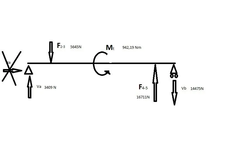
I have a problem with the sizing of a reference shaft of a coaxial reducer: How do the forces exchanged between the dentate wheels act on the tree? Are they discord or agree? I attach to the discussion the pattern of my problem.

thanks to all
 

Attachments

  • Cattura1.webp
    Cattura1.webp
    14.5 KB · Views: 62
I would say that you simply have to make the balance of the forces that exchange the pinions.
What do you mean by agreement/discord?

2 with 3 forces exchange, 4 with 5 forces exchange.
Therefore, according to the direction of rotation, you find how the forces, verses, modules and directions are exchanged.
simple.
 
Sorry but it seems like a simple machine construction problem.
as gerod said you have the forces acting on each single wheel and of course you have to disassemble them in the 2 components also depending on the angle of propeller of rotation to determine the direction.
 
Let's remember he's a student, if he knows everything, he wouldn't have to study!

However, as gerod and davide75 said, you have to find the forces that transmit between them the dense wheels.
to do this, admitting you to know the power and number of turns in or out, find the pair (p = c * omega). then knowing the primitive diameters of the toothed wheels, concoding also the angle of the propeller and the pressure angle find the force applied between the teeth that generates this pair. (f = c/r with addition all a beautiful sequela of breasts and things).
At that point, you know the forces applied on each tree that you can treat as a simple beam supported to the extremes (guards) with applied forces and concentrated moments.
 
first of all thanks to all of the answers.
in my problem toothed wheels are straight teeth so the shaft is loaded by a tangential force and a radial for the torque of 2-3 wheels and for the torque 3-4. then combine the radial force with the tangential force (with pitagora) and I get two total efforts. So the shaft on which the wheels 3 and 4 are mounted is loaded as in the image attached to this post?

thanks again and excuse me the inaccuracy
 

Attachments

  • Immagine.webp
    Immagine.webp
    4.9 KB · Views: 33
first of all thanks to all of the answers.
in my problem toothed wheels are straight teeth so the shaft is loaded by a tangential force and a radial for the torque of 2-3 wheels and for the torque 3-4. then combine the radial force with the tangential force (with pitagora) and I get two total efforts. So the shaft on which the wheels 3 and 4 are mounted is loaded as in the image attached to this post?

thanks again and excuse me the inaccuracy
not exactly, in which the forces due to wheels 3 and 4 will have towards each other the opposite. then in the tree section between wheels 3 and 4 of course you will also have the twisting moment.
If the wheels are straight, the component facing the axis of the beam is nothing.
 
So the pattern would be like that?

Thanks again
 

Attachments

  • Immagine.webp
    Immagine.webp
    9.7 KB · Views: 33
So the pattern would be like that?

Thanks again
apart from the numbers I didn't verify, I think so.
then you should see whether to consider the bearings as simple supports or as recesses. Considering them as inks, as they are partially, actually makes the hyperstatic beam so the problem becomes much more difficult to solve. Considering the bearings as a hinge supports makes life easier and is also in favor of safety (i.e. the stresses and deformations you will find from the calculation will be greater than the real).
last note: Your problem isn't slow, as f2-3 and f4-5 don't lie on the same floor.
 
In fact, if you solve the scheme according to the two floors you will have the results according to 2 orthogonal planes in which you can find the moment. So remember that if you ever have to check the section of the tree or find the suitable bearing to use you must consider as a total result that due to the scale sum of the 2 resulting found, including any moments.
the total result will be given by the root of the sum of the squares of the resulting
 
last note: Your problem isn't slow, as f2-3 and f4-5 don't lie on the same floor.
That's right.
it is better to make a three-dimensional scheme with the components of forces so as not to forget anything.
on the supports the torque is discharged only for the quantity due to the volunting friction that is generally little stuff.
 

Forum statistics

Threads
44,997
Messages
339,767
Members
4
Latest member
ibt

Members online

No members online now.
Back
Top