• This forum is the machine-generated translation of www.cad3d.it/forum1 - the Italian design community. Several terms are not translated correctly.

regauro

  • Thread starter Thread starter Erikilrosso
  • Start date Start date

Erikilrosso

Guest
I am following a restoration work for which I have to give the three-dimensional model of the fact state with possible rendering.
the notebooks of relief, manual, report all the characteristics and conditions of the property and I need to build the views in revit.
I must therefore use images of the masonry, plasters and various materials as equal to the original and corresponding to the reliefs; for this the ideal would be to photograph the original so use it in revit. but I didn't find anywhere how to import these images. here in the forum in the guide of revit.
the masonry, of course, are variable section and normally, out of lead and out of squad, have different compositions and external finishes variable also on the same parade. join them evenly with the appropriate command, it is an enterprise.
the three-dimensional representation of a wooden roof with roof covering at variable quotas, tilted or round square beams (trons), dots, unaligned currents and variable section, coverings of different materials, etc. represents a prestigious game.
then we do not talk about floorings with different materials and at different altitudes, sometimes barrel or cross on irregular plants (but a square plant!).
then there are the locks, the details in stone and wood, etc. etc.
maybe I was wrong to use revir?:confused:
 
you can change the image associated with a material, using the editor of materials. (see illustration).

about the model of the building, you can do it in revit; it is only need more time to do it.
 

Attachments

  • 11-24-2012 6-46-14 AM.webp
    11-24-2012 6-46-14 AM.webp
    50.3 KB · Views: 38
hi, I believe that the walls can still be made as solid or of union or union on path, for the facade materials I would have an idea but I should first make a test.
 
I would think for the walls of an adaptive family to which you will be assigned the Pillar category. If the building is very large this should give you way to maintain the manageable file and manage the stratigraphy of the walls, so you can assign the materials you need with more ease.

the idea is of tristan but I do not remember if posting on his blog or somewhere else.

Are you there?:biggrin:
 
I tried to make a wall with solids of union a little slippery
this entailed a façade with front rigged by flat faces varied and some with small twists for which not flat
turning a photo (of my face, they are megalomaniac) into material I found that the image was repeated from every corner of every face so that this is not feasible.
Trying as a decal, the image is seen only on the plane of the face on which it is placed
I think this is the limit of revit mappings.
a solution I think it's post-production, open the image in perspective of rendering your facade and overlap the photo of the facade taken pressapoco from the same point of view and then drag the grip of the edges of the photo on the edges of the building for
I'm gonna raise it up exactly.
regarding the 3d reconstruction of the building you have to understand if you already have a relief or you have to do it
 
I tried to make a wall with solids of union a little slippery
this entailed a façade with front rigged by flat faces varied and some with small twists for which not flat
turning a photo (of my face, they are megalomaniac) into material I found that the image was repeated from every corner of every face so that this is not feasible.
Trying as a decal, the image is seen only on the plane of the face on which it is placed
I think this is the limit of revit mappings.
a solution I think it's post-production, open the image in perspective of rendering your facade and overlap the photo of the facade taken pressapoco from the same point of view and then drag the grip of the edges of the photo on the edges of the building for
I'm gonna raise it up exactly.
regarding the 3d reconstruction of the building you have to understand if you already have a relief or you have to do it
I didn't know you wrote that you already had the relief.
 
the relief I had in dwg, in addition to a cloud of points of a laser relief that I could not open because in .pod format and that with revit does not dialogue. I also downloaded pointools view but did not serve me.
I would not have used revit, but then I have to work on it to produce the restoration project tables, so I don't know how to do otherwise.
I assure you then that succeeding in making some down-stage cruise vaults on an irregular plan is an enterprise and 9 times out of 10 do not.
I am losing a lot of time, much more than I would have used at the drawing table.
 
Sorry about ignorance, but are you creating those times directly in revit or are you simply importing from autocad?
because I also had probl not recently for Gothic cruises with arches of equal size only to 2, ribs etc, although autocad managed to create decent sails. ..pected that the different management of geometries in max crei of tensions difficult to eliminate on some parts of the time. When I have time I try to import them into revit and see what comes out.. .
Let us know
 
I tried to do some times, definitely with autocad mesh is easier, 2 are simple, the third are all four different half parables with equal height and the basic form is trapetidal
 

Attachments

  • VOLTA.webp
    VOLTA.webp
    164 KB · Views: 31
with revit I managed to get something that looks like the relief, I created a floor of the thickness of the time, then for a first time:
generic models > empty extrusion > path design > path design > profile 2 > cut geometry.
I said it again. the result is appreciable.
the problem arises when the two profiles are not parallel and therefore, the path is not perfectly straight as you can not cut the blank extrusion solid from the floor.
Do you have any ideas about it?
the fact is that the existing has the straight axis and faces are not parallel.
 
with revit I managed to get something that looks like the relief, I created a floor of the thickness of the time, then for a first time:
generic models > empty extrusion > path design > path design > profile 2 > cut geometry.
I said it again. the result is appreciable.
the problem arises when the two profiles are not parallel and therefore, the path is not perfectly straight as you can not cut the blank extrusion solid from the floor.
Do you have any ideas about it?
the fact is that the existing has the straight axis and faces are not parallel.
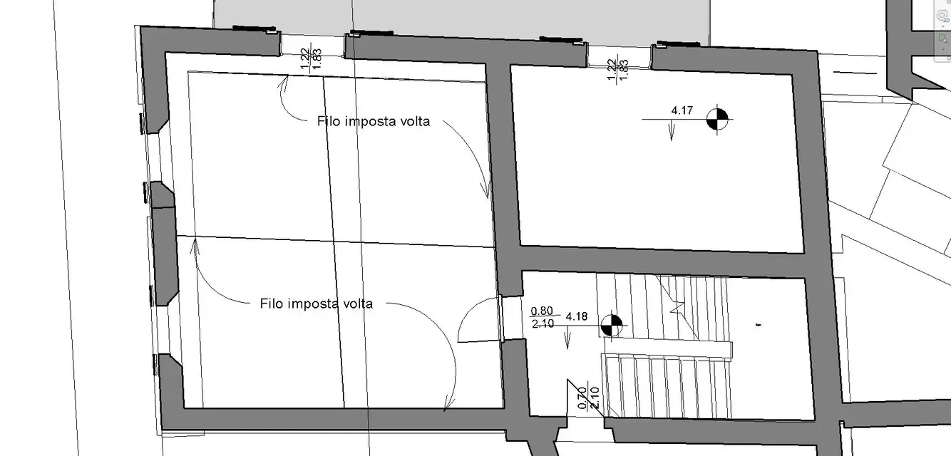
put the planimetry of one of these times, do not just have fun: mad:, let us have some fun also bored (as he said totò):tongue:
 
If you see the first time in the image I put, it does not have a parallel side, with some little cunning I managed to do it.
That is why I ask you the data of once, to apply the same cunnings.
Maybe later I'll give you a tutorial
 
Sorry I'm late to make, I'm going to attach the plan of the times that, I don't know why I don't see anymore. the plant is that of the first floor whose floor consists of the vaults, which have a smaller perimeter of the floor itself, since the walls of the ground floor are of greater width than the above (clear no...... ? )
I'm almost thinking of using revit (2012).
 

Attachments

  • Volte.webp
    Volte.webp
    52.2 KB · Views: 32
I did some evidence.
some stuck on solids in subtraction
These 4 were working
not having height data of the time
I gave h 180 cm
 

Attachments

  • Volte 3d.webp
    Volte 3d.webp
    197.9 KB · Views: 36
what I get is more or less similar to the second model from the right. the thickness of the block from which I dug the times is equal to m. 1.49. estimated but not detectable, above there are certainly about 11 cm of flooring, between background and floor, so to form a package of about 1.50 m. the thickness of the vault, made of barbed brick, can vary between 15 and 25/30 cm, but we are not sure. We should have a hole but they don't leave us.
Sure that to look at your models you make me want to go back to the drawing table and the pencil...:biggrin:.
 
in the first two but they didn't come back, as you can see from the file I sent you, the crossing lines of the times, because of the diversity of light of each bow to the sides,
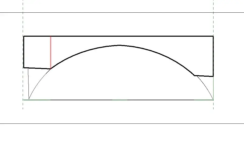
2 seconds I made them thinking that in the end over drawings anyway the layered floor and the arches serve only to see the lines in section and where you can graphically add the thicknesses
red line is the diagonal line of the split solid that I made invisible
as on the other side
 

Attachments

  • Volte sezione.webp
    Volte sezione.webp
    7.9 KB · Views: 8
looking well also in the fourth "time" there are differences between the intersections of the arches
I think that the 3rd "time" is the most corresponding to reality and was also the fastest to do. an extrusion with "union" and always with "union" the subtraction of the second "time"
the difficult was to build the basic lines to frame the room
 
hi render, I only live now after a few months because I had some trouble.
In the end I managed to create the model of the building, of which I did not provide the renders, however, and I used it to present the preliminary. of course after the "technical" times (3 months) we were asked for the final in 18 days. It was a business to assemble all those pieces of floors, walls and wood.
Fortunately it is a small property, so we won't have to have a problem with respecting the times.
thanks for advice and times.
 
hi render, I only live now after a few months because I had some trouble.
In the end I managed to create the model of the building, of which I did not provide the renders, however, and I used it to present the preliminary. of course after the "technical" times (3 months) we were asked for the final in 18 days. It was a business to assemble all those pieces of floors, walls and wood.
Fortunately it is a small property, so we won't have to have a problem with respecting the times.
thanks for advice and times.
thank you for your thanks,
However all evil does not come to harm
next Wednesday I will go to Piedmont with the architect in charge to see a small castle to be transformed into residence (26 rooms + common parts) so the study of the times will definitely be useful, let's say that the 3d draft of the walls I have already made to make some demonstration plans of the distribution of the rooms.
I think it'll be fun. http://www.cad3d.it/forum1/images/icons/icon11.pn
render
 

Forum statistics

Threads
44,997
Messages
339,767
Members
4
Latest member
ibt

Members online

No members online now.
Back
Top