• This forum is the machine-generated translation of www.cad3d.it/forum1 - the Italian design community. Several terms are not translated correctly.

relatable surfaces

  • Thread starter Thread starter XAM
  • Start date Start date

XAM

Guest
Good evening,
this is my first intervention in this forum from which I often "active" knowledge.
I am a self-taught in solid works 2007 and therefore forgive evetuali inaccuracies as I go to expose.

So, I would like to model a small steel ship (a precision vessel) and I would like to have a few tips on how to set the job.
I imported the hull surface and then created a series of planes (like reference geometry) in correspondence of the ordinates and bridges.
now in order to realize the structures to bandage I used "division line" (in intersection mode) between famine sup and neat plane. so I completed the sketch made of the intersection line with the rest of the contour of the rib that I then extruded to give thickness to the structure.

Unfortunately, however, the "division line" actually divides the famine sup into two parts... and continuing to add structures the famine sup is reduced to a cluster of confetti impossible to manage.

I think that the road I followed is not the best. ideally I would like to be able to generate the rib as a single part, keeping the hull surface as "referable" or "xref" to use the auticad terminologists. is this possible in solid works?

Thank you in advance!
 
can you post images of what you got and what you want and even better the file to help you better?
 
Try to look at the "intersection curve" command in the online guide, I think it's your case.
 
Thank you very much, indeed with "intersection curve" the problem is resolved. (I don't know why I was fossilized on that division line...:mad:)

I attach the image of the model: I made a horizontal blade at the sky of the double bottom, and another at the bridge. between the two it was easy to create the profile of the rib.
so I copied the sketch of the first rib on the other ordered getting quickly the new ribs (there will be only a little work to adapt the sketches to the fasciame and reset the relations). Thanks again.

I'd like to go a little further (I'm convinced that solid works is much more powerful than some software, which I know discreetly, dedicated to naval structures and I would like to be able to understand what the limits are).

then: Is there a way to show only a "full" of the model? this would be convenient to work, for example, on a single rib without seeing the others. orienting the view from prora, for example, the various ribs are almost and it is difficult to intervene on the desired one.
I thought I'd fix it by flying and making sections, but from the design section I can't change the sketches.
Alternatively, I tried to use the "section view" (the one with the cylinder's icon) but I can't delimite the section in two ways. i.e. if I put myself on the ordered plane 24 he cuts me all that is in the stern of the 24 but he continues to show me everything that is prora (or vice versa).
Now I'm using a small test model, but on a real rib there may be hundreds.
 

Attachments

  • part1.webp
    part1.webp
    30.2 KB · Views: 31
Thank you very much, indeed with "intersection curve" the problem is resolved. (I don't know why I was fossilized on that division line...:mad:)

I attach the image of the model: I made a horizontal blade at the sky of the double bottom, and another at the bridge. between the two it was easy to create the profile of the rib.
so I copied the sketch of the first rib on the other ordered getting quickly the new ribs (there will be only a little work to adapt the sketches to the fasciame and reset the relations). Thanks again.

I'd like to go a little further (I'm convinced that solid works is much more powerful than some software, which I know discreetly, dedicated to naval structures and I would like to be able to understand what the limits are).

then: Is there a way to show only a "full" of the model? this would be convenient to work, for example, on a single rib without seeing the others. orienting the view from prora, for example, the various ribs are almost and it is difficult to intervene on the desired one.
I thought I'd fix it by flying and making sections, but from the design section I can't change the sketches.
Alternatively, I tried to use the "section view" (the one with the cylinder's icon) but I can't delimite the section in two ways. i.e. if I put myself on the ordered plane 24 he cuts me all that is in the stern of the 24 but he continues to show me everything that is prora (or vice versa).
Now I'm using a small test model, but on a real rib there may be hundreds.
there are various methods to design your shores.
one is what has indicated you, even if I avoid where possible conversions as it adds approximation (surfaces) to other approximation (intersection curve converts).
copy sketches to edit them no.
You could create a master sketch that contains your profiles and then extrude them at different distances.
or use the ribbing function.
or use repetitions with surface replacement.
or work completely on the surface.
or... .
experiment and decide which is the most convenient.
 
thanks for the answers.

some evidence I had already made, however, the suggestions are well accepted. I will test what comes out with ribbing (I had seen this function and did not seem suitable, however I will do further tests).
working only with the surfaces I don't think it is suitable for my case, at finished work I would need to calculate weights and baricentres. . .

I would like to maintain the setting of the transversal planes in accordance with the orderly and as many longitudinal ones in correspondence of the "main" structures (sitting in detail I mean the rings formed by paramezzali/montanti of bulkhead/anguille).
this because the set of plans so defined constitutes a system of reference of the ship structure to which it is difficult to give up.

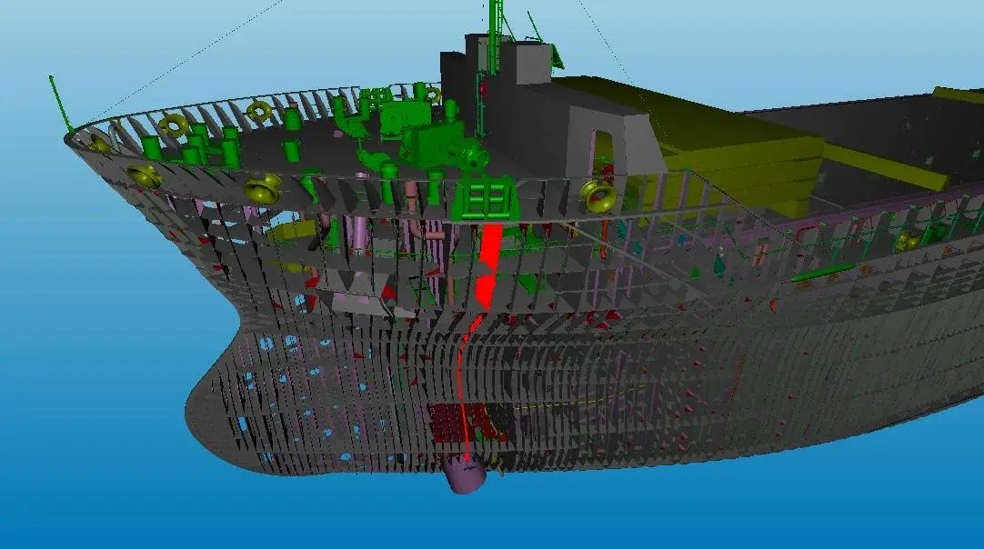
I attached an image taken from the site of a Dutch naval engineering study (http://www.vuykgron.nl/). It is a model made (I believe) with nupas cadmatic and is what I would aspire to arrive. as you see the structures are very dense, it is very difficult to move within the model. I colored red a rib... in a hypothetical model of the genre made in solid works I would like to find the way to cut a slice of the model 50mm forward and 50mm behind the plane of the red rib so that we can work. Is it possible?
 

Attachments

  • md727.webp
    md727.webp
    78.9 KB · Views: 28
thanks for the answers.

some evidence I had already made, however, the suggestions are well accepted. I will test what comes out with ribbing (I had seen this function and did not seem suitable, however I will do further tests).
working only with the surfaces I don't think it is suitable for my case, at finished work I would need to calculate weights and baricentres. . .

I would like to maintain the setting of the transversal planes in accordance with the orderly and as many longitudinal ones in correspondence of the "main" structures (sitting in detail I mean the rings formed by paramezzali/montanti of bulkhead/anguille).
this because the set of plans so defined constitutes a system of reference of the ship structure to which it is difficult to give up.

I attached an image taken from the site of a Dutch naval engineering study (http://www.vuykgron.nl/). It is a model made (I believe) with nupas cadmatic and is what I would aspire to arrive. as you see the structures are very dense, it is very difficult to move within the model. I colored red a rib... in a hypothetical model of the genre made in solid works I would like to find the way to cut a slice of the model 50mm forward and 50mm behind the plane of the red rib so that we can work. Is it possible?
Yes, with this command directly together or part
http://help.solidworks.com/2011/ita...p/sldworks/display/section_view_in_models.htmyou can also use display states to hide what you don't need.
[youtube]57u95q0€[/youtube]
 
thanks for the answers.

some evidence I had already made, however, the suggestions are well accepted. I will test what comes out with ribbing (I had seen this function and did not seem suitable, however I will do further tests).
working only with the surfaces I don't think it is suitable for my case, at finished work I would need to calculate weights and baricentres. . .

I would like to maintain the setting of the transversal planes in accordance with the orderly and as many longitudinal ones in correspondence of the "main" structures (sitting in detail I mean the rings formed by paramezzali/montanti of bulkhead/anguille).
this because the set of plans so defined constitutes a system of reference of the ship structure to which it is difficult to give up.

I attached an image taken from the site of a Dutch naval engineering study (http://www.vuykgron.nl/). It is a model made (I believe) with nupas cadmatic and is what I would aspire to arrive. as you see the structures are very dense, it is very difficult to move within the model. I colored red a rib... in a hypothetical model of the genre made in solid works I would like to find the way to cut a slice of the model 50mm forward and 50mm behind the plane of the red rib so that we can work. Is it possible?
thanks to the image, now I'm more clear about your intent.
First of all, don't think about managing everything like a solid.
It would become heavy and unmanageable both at the level of file size and understanding.
the ship must be divided into design compartments.
using surfaces is the best way.
You could create the shape of the ship with the surface.
your crosses as a repetition of flat faces.
another surface that would be the inner part that shapes your coasts and eventually cuts everything between them.
then create a new file and import some surfaces that you will thickness.
 
I know this command a bit, and that's what I thought of using, only that I can't (also using 2 sections) cut only one slice of the model. I would like to see only a model area between xmm forward and behind a superfice date.

the use of visualization states instead seems more difficult to act.
SolidUser said:
First of all, don't think about managing everything like a solid.
It would become heavy and unmanageable both at the level of file size and understanding.
the ship must be divided into design compartments.
my idea would be to find the way to reduce the depth of view and then make a macro (me the cable well in vba and hope to succeed) that allows to "set" the order on which you want to work. (always speak of order but the same applies to longitudinal bulkheads and bridges).
once this aspect is in place I would like to find the way to realize the individual sub-assistances (usually made up of some sheets+frames+profiles) as single parts...
 
I know this command a bit, and that's what I thought of using, only that I can't (also using 2 sections) cut only one slice of the model. I would like to see only a model area between xmm forward and behind a superfice date.
Maybe he didn't look well at all the options.. .
use of display states instead I think it's more difficult to act..
How much? ?
selections from the tree the bodies/parts you want to hide and the game is done.
However yours is a case in the section... download the file and look.
you can, rotate, move and tilt all the sections you want.
 

Attachments

Sorry the banality of the question... What do you want to get at the end? What is the purpose of your project? Do you need to get carpentry + normal designs for details?

is not a simple job to do and it serves good familiarity with the tools of swx.
 
@ mike1967: thanks, tomorrow I unload the file and I see to understand something. When it comes to visualization states, I mean they are not as efficient, but I would rather be able to "enter" on an orderly date rather than hide the rest. However, my idea comes from the way of working software that I currently use. . Perhaps it could be useful to deepen this aspect too. as I have some time I will certainly try.

@re_solidworks: My aim is to see how far the process of producing executive documentation of hull can be achieved by using solid works. all in all some software for naval structures are based on autocad or similar (and in some case it is really little discosatno).
 
Thank you very much for the movie mike1967. I was wrong because I was leaving with both sections from the default front floor!!
 
my idea would be to find the way to reduce the depth of view and then make a macro (me the cable well in vba and hope to succeed) that allows to "set" the order on which you want to work. (always speak of order but the same applies to longitudinal bulkheads and bridges).
once this aspect is in place I would like to find the way to realize the individual sub-assistances (usually made up of some sheets+frames+profiles) as single parts...
definitely a macro facilitates your work.
However the section command can be saved as a view and then you can call it back with the space bar whenever you want.
In addition, if you edit the sketch, automatically solidworks hides that in front of the sketch plane.

As for the design, the part must be a kind of layout of your transverses.
from there create a part that groups a work area.
do a part with all the crossings of the ship, it becomes very honorable in all senses, ability to understand and manage changes.
 
Thank you very much for the movie mike1967. I was wrong. because I started with both sections from the default front floor!!
I was sure... :rolleyes:


Did you read my message in the presentation area?? :smile:

Hi.
 
Did you read my message in the presentation area?? :smile:

Hi.
horror and abomination a rotor with an inverted shovel! I will correct, thank you. :smile:
SolidUser said:
do a part with all the crossings of the ship, it becomes very honorable in all senses, ability to understand and manage changes.
In fact it was precisely to avoid the sure excessive complexity that I wanted to discover the possibility of using the hull surface as a reference.
 

Forum statistics

Threads
44,997
Messages
339,767
Members
4
Latest member
ibt

Members online

No members online now.
Back
Top