• This forum is the machine-generated translation of www.cad3d.it/forum1 - the Italian design community. Several terms are not translated correctly.

round nylon rack wheel

  • Thread starter Thread starter micvendak
  • Start date Start date

micvendak

Guest
Good morning to all,
from the last time I wrote I made progress in sw.. but not so many to solve problems like this.
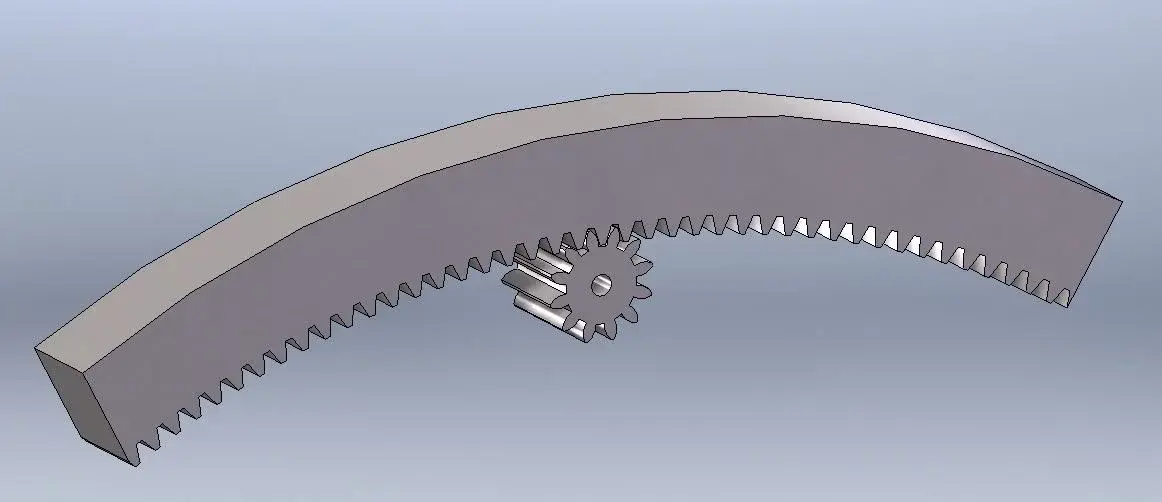
I have to make a dentate wheel in nylon or polyethylene that will gear on a rack always in nylon or polyethylene that follows a curved path.
the gear in practice I think it is possible because, despite the curve the rack, the contact surface with the teeth of the wheel is at least 1.5 cm.
advice on this?
Could it also work on materials?
But I can't proportionalize the system. Does anyone have a rack wheel mating as set?
Thank you.
ps I have 1 day time to finish all helpppp :confused::bekle::eek:
 
Good morning to all,
from the last time I wrote I made progress in sw.. but not so many to solve problems like this.
I have to make a dentate wheel in nylon or polyethylene that will gear on a rack always in nylon or polyethylene that follows a curved path.
the gear in practice I think it is possible because, despite the curve the rack, the contact surface with the teeth of the wheel is at least 1.5 cm.
advice on this?
Could it also work on materials?
But I can't proportionalize the system. Does anyone have a rack wheel mating as set?
Thank you.
ps I have 1 day time to finish all helpppp
Sorry, I think I didn't understand... Would you like to dip a rack to get her on a curved path?
the gear in practice I think it is possible because, despite the curve the rack, the contact surface with the teeth of the wheel is at least 1.5 cm.
is the width of the tooth 15mm?
Could it also work on materials?
Sorry, what materials?
But I can't proportionalize the system. Does anyone have a rack wheel mating as set?
I mean, can't you place it with the constraints?
ps I have 1 day time to finish all helpppp
What is it?
 
I didn't understand your problem. if you use the wheels and swx racks I will never work the gear because they have no evolving profiles but only simplified profiles. I recommend using other dedicated application for the creation of dense wheels.
 
... the gear in practice I think it is possible because, despite the curve the rack, the contact surface with the teeth of the wheel is at least 1.5 cm...
I've got a little... but in this case more "street" is the dense band better would be for the path in the curves.

to model it exactly modular (correct evolving profile) you care little; you can try to simulate a "fittizia a pleasure" toothing.

look at this discussion a few days back http://www.cad3d.it/forum1/showthread.php?t=27466; The rack can build it like that, considering the teeth as the snags of that tape.

greetings
Mar
 
If the rack is curved and you have a pinion, according to me it is reported to the case of 2 toothed wheels of which the rack is a very large wheel segment inside or outside.
 
If the rack is curved and you have a pinion, according to me it is reported to the case of 2 toothed wheels of which the rack is a very large wheel segment inside or outside.
That's true, too.
but who knows why I thought about the rack with teeth on the "top face" and not inside:biggrin:.

In this case there would be no problem as you say with internal gears.

greetings
Mar
 
Sorry, I think I didn't understand... Would you like to dip a rack to get her on a curved path?exactly. the rack will not be straight but will follow a curved path, so clearly I will not see it working in solidworks. if there is a good proportion, and since being the very wide bending radius the contact surface between the teeth of the wheel and those of the rack is enough to result almost a straight rack.is the width of the tooth 15mm?
No.

Sorry, what materials?
nylon or polyethylene

I mean, can't you place it with the constraints?
No, the constraints have nothing to do with it. I don't find a proper proportion of the rack wheel. Also because I don't have a mechanical manual with me. I was looking for something ready.
 
If the rack is curved and you have a pinion, according to me it is reported to the case of 2 toothed wheels of which the rack is a very large wheel segment inside or outside.
That's right. I think you got the point. I was looking for an example of the pre-existing genre.
 
That's right. I think you got the point. I was looking for an example of the pre-existing genre.
So let's see what you need exactly.

- know the pairs and powers at stake
- analyze each piece of rack curve as a piece of wheel conducted at large known radius
- for module sizing and pinion width you have to use statically the formula of lewis (imposed m and revenues b having known z, mt, flexional sigma)
- possible fatigue test and pitting according to standard (one 8862 or iso 6336)
- if you want to simplify the whole look for the zipper post with racket a few days ago that there is my scheme with forces

find almost everything around the forum and what is not here just googular. At least you know what and how to proceed.
 
so clearly I will not see it working in solidworks..
I'm sure you can see it working in swx.
it is not a rack but a "segment" of internal toothing wheel.

If you provide some "technical" and dimensional data (and maybe a box..) we can help you better.

greetings
Mar
 
..certo che puoi tranquillamente vederla funzionare in swx.
non si tratta di cremagliera ma di un "segmento" di ruota a dentatura interna.

se fornisci qualche dato "tecnico" e dimensionale (e magari uno schemino..) possiamo aiutarti meglio.

saluti
marco

grazie del vostro aiuto.
sono alla fase precedente. devo ancora proporzionare l'accoppiamento. non sto riuscendoci in quanto ho difficoltà a lavorare con lo schizzo 3d con il quale cerco di disegnare i denti sulla cremagliera tonda.
cercavo in rete un esempio di proporzionamento di questo ruotismo.
non so da dove iniziare.
appena avrò proporzionato magari posto qualche immagine..anzi ci provo adesso..così capite.
grazie
 

Attachments

grazie del vostro aiuto.
sono alla fase precedente. devo ancora proporzionare l'accoppiamento. non sto riuscendoci in quanto ho difficoltà a lavorare con lo schizzo 3d con il quale cerco di disegnare i denti sulla cremagliera tonda.
cercavo in rete un esempio di proporzionamento di questo ruotismo.
non so da dove iniziare.
appena avrò proporzionato magari posto qualche immagine..anzi ci provo adesso..così capite.
grazie

a direi il vero non ci si capisce una cippa nel pdf allegato :tongue:

denti sulla cremagliera tonda? e' un arco di ruota interna se mai o esterna se girata. usare le toolbox e avrai tutto sempre se non fai le montagne russe con la cremagliera.

schizzo 3d ma per fare cosa???
 
questo in allegato può essere quello che devi realizzare?
 

Attachments

  • cremagliera curva.webp
    cremagliera curva.webp
    25.6 KB · Views: 14
... non sto riuscendoci in quanto ho difficoltà a lavorare con lo schizzo 3d con il quale cerco di disegnare i denti sulla cremagliera tonda.
perchè 3d?? quei denti li "tagli" con un normalissimo schizzo 2d.
potresti spiegare meglio in cosa ti stai cimentando? perchè effettivamente quel pdf che hai postato non è molto chiaro.

saluti
marco
 
mi sa tanto che non è nemmeno come la mia immagine di prima. guardando bene il pdf non ha gli assi di rotazione paralleli ma, pare, perpendicolari. quindi li serve una coppia conica...
hi_a1208.jpg
 

Forum statistics

Threads
44,997
Messages
339,767
Members
4
Latest member
ibt

Members online

No members online now.
Back
Top