• This forum is the machine-generated translation of www.cad3d.it/forum1 - the Italian design community. Several terms are not translated correctly.

rubber membrane

  • Thread starter Thread starter gianni_ing
  • Start date Start date

gianni_ing

Guest
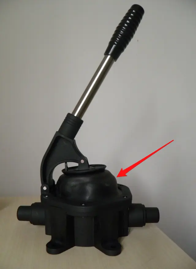
Hello everyone, I need help. I am making with solidworks 2009 a manual diaphragm pump (photo attached). my problem is to make the rubber membrane (indicated in the photo by the arrow). is it possible to make the membrane itself flexible in such a way that it, when pushed down from the lever, curves? I hope I've explained clearly.
Thank you in advance.
 

Attachments

  • PA190018.webp
    PA190018.webp
    700.1 KB · Views: 51
I would say modeling is purely static solid. it is not possible to model elastic elements that follow the deformation laws. with the fem it is possible to see large and small movements. you could use the maximum deformed model to exalt them as a body and insert it into the 3d but you will never get what you asked for.
 
you can easily do with animation software type 3ds.
However, let's understand, for the design, these things are not only not required, but personally if I see hours of design paid by me and expenses for "abbellishments" of this kind, I start to piss off. . .

p.s.
Where is the presentation in the special area? Did you read the rules?
Please...we start with the right foot...:mixed::finger:
 
Hello everyone, I need help. I am making with solidworks 2009 a manual diaphragm pump (photo attached). my problem is to make the rubber membrane (indicated in the photo by the arrow). is it possible to make the membrane itself flexible in such a way that it, when pushed down from the lever, curves? I hope I've explained clearly.
Thank you in advance.
If you need an animation, I don't know, but if you need a semi-adapted geometry, take a look at the annex. It is an extrusion of loft, in which the initial and final plans are bound to stand on the parts that "command". if you change the members' posizoni the loft is updated (maybe you have to press the light), at least until we stay in non-extreme deformations.

It's obviously not strict, but it can be serious about making the idea.

If you want to make a bellow, just add other sections to the extrusion (look at the help online where it is explained how to do). the planes where these profiles are located then you could place them in a parametric way compared to the position of the levers, in this way you will see the various headsets that will go behind the plans you have defined.

Have fun! :smile:

p.s. I saw you have solid 2009, the example is done with 2010, I'm sorry. I hope you know what I mean, I'll get you an image.
 

Attachments

  • membrana.zip
    membrana.zip
    262.7 KB · Views: 26
  • loft.webp
    loft.webp
    102 KB · Views: 44
If you model an object with the method that suggested you hunter in the context when you do animation with the study of movement you see it move correctly. in fact the model is moved, rebuilt and then the frame is captured.
this allows you to see it move even if with manual movements does not work in real time.
 
If you need an animation, I don't know, but if you need a semi-adapted geometry, take a look at the annex. It is an extrusion of loft, in which the initial and final plans are bound to stand on the parts that "command". if you change the members' posizoni the loft is updated (maybe you have to press the light), at least until we stay in non-extreme deformations.

It's obviously not strict, but it can be serious about making the idea.

If you want to make a bellow, just add other sections to the extrusion (look at the help online where it is explained how to do). the planes where these profiles are located then you could place them in a parametric way compared to the position of the levers, in this way you will see the various headsets that will go behind the plans you have defined.

Have fun! :smile:

p.s. I saw you have solid 2009, the example is done with 2010, I'm sorry. I hope you know what I mean, I'll get you an image.
all, the loft is hurt as the proposed driving curves are related to the location where you clicked to select the curves.
the advice I give you is to add a point in one of the 4 notable points of the circles and at this point you drag the green spots until they hook to the point.
This will generate a better loft.
 
you can do by simulating a path that you will then put in transparency.
Call me I'll explain to you in private byby
 
you can do by simulating a path that you will then put in transparency.
Call me I'll explain to you in private byby
apart from writing in uppercase is yelling, if you don't want to share information with the users of the forum you have just wrong place or at least you don't understand the purpose.
:cool:
 

Forum statistics

Threads
44,997
Messages
339,767
Members
4
Latest member
ibt

Members online

No members online now.
Back
Top