• This forum is the machine-generated translation of www.cad3d.it/forum1 - the Italian design community. Several terms are not translated correctly.

section and deduction

  • Thread starter Thread starter braunfish
  • Start date Start date

braunfish

Guest
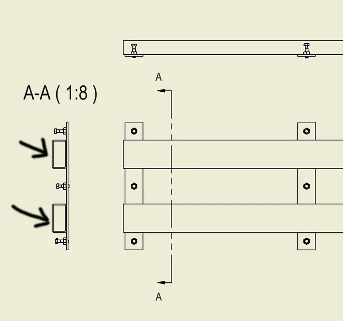
in any project I work, when in a drawing I carry out a section of a part taken from the center contents (in this case 2 tubes with rectangular section), the sectional profile is never drawn (see photo).
in the section settings the dash is active.

Any ideas?
 

Attachments

  • Assembly1.webp
    Assembly1.webp
    14.2 KB · Views: 22
because inventor (justly) sees the forms generated by the c.c. as standard parts, then not to be dissected (see example rounds or plates), if you want to sharpen, you must select the parts that interest you with the filter in priority part - button dx and participates in the section: or double-click the view - options - standard parts in section - always. in the latter way all the view and its components of the c.c. will be included in the section, you must see your needs of the moment.
 
because inventor (justly) sees the form generated by the c.c. as standard parts, ............. .
rightly?
I don't think the design rules say that.
It seems to me that it is more a lack of the program, one of those little things that make me angry and that seem put there ready for the next releases.

Bye.
 
rightly?
I don't think the design rules say that.
It seems to me that it is more a lack of the program, one of those little things that make me angry and that seem put there ready for the next releases.

Bye.
inventor does not distinguish between forms of the center contained or for example bolts (makes of all the grass a beam) and norms say that bolts, trees in general, sticks etc.. Don't go in section.
I know that sometimes it's annoying, but the only way to solve it would be to tell c.c. what you want to include in section and what not when you edit c.c. itself.
p.s. and anyway it's a "problem" that you've been after forever so... or it's not a problem or no one has ever mentioned it to the autodesk
 
for screw-type stuff is right not to be dissected, but for tubulars.. .
I know well I use very many as I use a lot of carpentry in general and I repeat inventor does not distinguish between screws and carpenters in general everything comes from the c.c.
 
I know well I use very many as I use a lot of carpentry in general and I repeat inventor does not distinguish between screws and carpenters in general everything comes from the c.c.
we're saying the same thing, I didn't read your post because we wrote at the same time:
 
for screw-type stuff is right not to be dissected, but for tubulars.. .
That's why I don't use c.c. profiles.
I have, from rel 5, my 4/5 templates for various profiles ( parametrised and precut at 45° at the end ) and well that go:biggrin:

Bye.
 
go into options-> drawing--> standard sections of the sections and set it up always.
if it does so usually because there is set "observe browser settings".
 
Unfortunately this is a small setting that is not that immediately understood by the wording of the settings, but once set there are no more problems and quiet that the bolts do not cut off :)
Hi.
 
go into options-> drawing--> standard sections of the sections and set it up always.
if it does so usually because there is set "observe browser settings".
if you choose a section view and then:
- change of view
- display options
- standard parts section,
you can make the same choice you bring over without changing the application setting. Therefore, from "options" you can choose if to use a priori setting for all drawings, from "modification view" only the sez. desired.
cmq if I can say mine, I prefer (at least when not many components) to see the case by chance. For example, a seized bearing, with the split spheres not in the center, is very brute... .
 
Hi.

Sorry about the invasion but it seemed useless to me to open a new topic given the title of this... here is my question:

How can I do (invent 2010) to force all sectional restraints to 45°/-45°? ?

Thanks again
 
in the view sectioned in the table you go on the tractor and when you have "prese", button dx and edit. you will open the menu related to the hold where you can also change the type of deduction in addition to the angle and distance between the deduction lines.
Otherwise you have to create a style, if I don't remember badly, in which you want all the restraints to -45° but I rest that in all the masses on the table you will then have the restraints to -45°. If not you have to select one by one if you only want them for that table.... but why do you want them all to -45? ?
 
Hi.

since the legislation provides for sections of the section to 45 or -45 x metal materials (at least those in use in mechanics)

every time I have to perform the procedure you have described and that I already knew...xche when sections of the assemblies many of the pieces have inclined restraints with absurd angles...(not to be sure)
I wondered how I can associate with any material that the inventor proposes (or that I create) the restraint dissected to 45 (modifying automatically the distance of deduction x the pieces in contact... or even better between various pieces in contact he steps from 45 to -45... as you should always do!)

Thanks again
 
It's been a while I've been looking in the stil but I can't get out of it...for him all kinds of restraints (including those dopps etc) are at 45! you probably have to go ...bho! !
 
or better...the x way to associate a x-material dashboard I found it, but still does not keep the 45 degrees in the axiem environment (on neighboring pieces) but as I said before choose angles not to nor x differentiate the pieces!:mad:
 

Forum statistics

Threads
44,997
Messages
339,767
Members
4
Latest member
ibt

Members online

No members online now.
Back
Top