• This forum is the machine-generated translation of www.cad3d.it/forum1 - the Italian design community. Several terms are not translated correctly.

shape tolerances in displacement

  • Thread starter Thread starter folle76
  • Start date Start date

folle76

Guest
Hello.
I gave a splash on the forum about the rolling process, but I need more info.
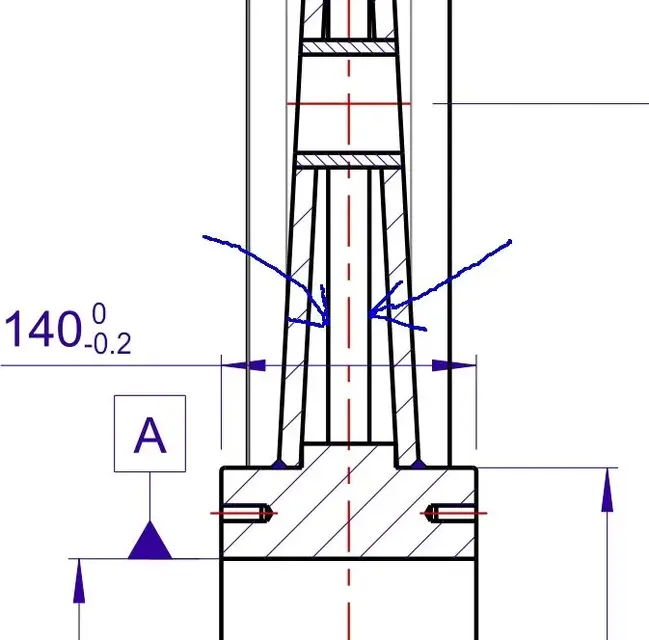
in the annex you can see the design of a pulley whose outer part is obtained from folded plate thickness 12 mm and then calandrated.
I know what technologically can be done. but, being a bit fasting of technology and geometric tolerances, what tolerance of circular oscillation in all directions is obtainable (see drawing)? In general, can you tell me what is the criticality of a similar technological process?
Thank you very much.
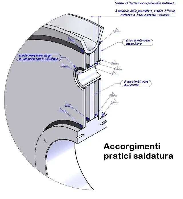
 

Attachments

Since you have to fold the plate, you will have to give tolerances on the fold angle, reasonably between the useful application and the possibility of the machine used.

Then the rolling will be done by hand in the sense that you use the small roller grille and inevitably there will be a deformation of the fold angle you previously tolerated.

later welded (at tig preferably at points) this band calandrata to the central hub and must be aligned by hand throughout the circular route and then closed the junction.

later it should be turned to the lathe with a comparison and measured the oscillation and correct the disbanded to half kg hammered soles.

if the operator has done everything well and has a good hand you can get to +/- 1 mm but... He must be good.

if all ok, it passes to the welding at times with profile thread welding on the hub, with additional tensions and deformations in the order of 0.5 mm.

a finite operation, with so much sweat, some invocation will come +/-1.5 until +/- 2 mm (in the best possible circumstances).

multiplies by the coefficient of inability 2, you will get +/- 4 mm, it is so much but you can not think about that size at all times. You should put yourself in the perspective of who has to do it.

when working in series then it is possible to build equipment to ensure that the sheet is correctly aligned with the hub, otherwise it is considerable costs.
personal opinion: for a reduced number of full-fledged wheels. for a high number it realizes equipment and optimizes the process of construction of the sheet metal band. consider that for a high number of wheels it could be possible to make the steel mold and to work it in the center.ps: You have tolerances to give also on the two disc plates that positions and balances...
 
I allowed you some notes and notes on your design. I put myself in the perspective of who has to make the piece.

I considered:

- two oxytaglio or laser laglio discs if you can sp = 12 mm
- Oxycut cental disc or laser cutting thickness from you not indicated but can be 20 mm
- two tubes cut at corner
- central hub turned and milled to make male holes

I've kept everything I think you need to be seen again. I usually carry out the 3d model following the stages of practical realization, so I always deliver executive drawings in all their parts, without leaving much freedom to the supplier. of course the strategies are agreed so as to facilitate to the supplier the realization and to have the design accurately reproducible in the same conditions from any supplier.
 

Attachments

  • ruota.webp
    ruota.webp
    104.7 KB · Views: 94
if you consider welding also the central disk you can not position the lateral discs in an angle. In my opinion the welding is indispensable to fix on a circular surface the throat. Moreover those central discs are lined with conical paitto and it takes a nice press to do so (conic escaped effect) and I think it is an unjustified cost as well as structurally useless.

holes should be made with cyanfrination for welding and be filled. these are all problems that if they are not foreseen by the designer they become grains and object of disguidi for the supplier who will be obliged to raise the crocodile and discuss the feasibility of the piece.
 

Attachments

  • disco.webp
    disco.webp
    76.4 KB · Views: 55
Excuse me, I say mine too:

Since all these shortcomings and processes are necessary (folding, rolling, welding, etc.) it is inevitable to have more processing phases, therefore different cycles.
could you not consider starting from full even for a very high number of pieces?
I'm sure it would cost a lot less and they would have far better tolerances.

What do you think?

edit: capers!!!! I had not seen the size.... I would say that starting from the full it would come, even with the due notices, to an excessive weight. I cannot imagine inertia
exact, considering the size or starting from a steel casting for high number, otherwise it should be welded which costs less
 
First of all I remain basic and allied by the omniscience of mechanicsmg. to give him the commission if we take the order of those pulleys. go to a very interesting place. . .
cmq, regarding your very interesting observations (because there is so little theory and so much practice) I wanted to give you additional information (please I don't have many) and ask for a conclusive opinion.
1) the pulley axis is vertical (according to the force of gravity would say one) and there is the possibility that the water should flow from the two holes therefore the length of those two tubes should not go out from the two folders of thickness 12 mm. how do I hold together those two tube brushes with the folders? internal welding? And if I want to avoid welding there, do you have any ideas?
2) probably tricked the section, but the central disk is not there: there are only the two side folders. Maybe I was wrong to make the 3d, though!!!! Are the two tags calandrated? I know. Oh, sorry, I'm reading now that they're ricalcati a conical plate, right?
I thank you for all the information even if I don't know how I'm going to counteract. . . As I get more info I'd be discussing it with you and the forum friends. Let's say that I would have preferred to get them full, but the client says that you can't.... but at least so I learn something.. .
Bye!
 

Attachments

  • ruota.webp
    ruota.webp
    117.6 KB · Views: 37
if you consider welding also the central disk you can not position the lateral discs in an angle. In my opinion the welding is indispensable to fix on a circular surface the throat. Moreover those central discs are lined with conical paitto and it takes a nice press to do so (conic escaped effect) and I think it is an unjustified cost as well as structurally useless.

holes should be made with cyanfrination for welding and be filled. these are all problems that if they are not foreseen by the designer they become grains and object of disguidi for the supplier who will be obliged to raise the crocodile and discuss the feasibility of the piece.
You say chill and weld? Do you think that working in the environment with brackish water there are special problems or shortcomings for welding?
Thanks again.
 
First of all I remain basic and allied by the omniscience of mechanicsmg. to give him the commission if we take the order of those pulleys. go to a very interesting place. . .
cmq, regarding your very interesting observations (because there is so little theory and so much practice) I wanted to give you additional information (please I don't have many) and ask for a conclusive opinion.
1) the pulley axis is vertical (according to the force of gravity would say one) and there is the possibility that the water should flow from the two holes therefore the length of those two tubes should not go out from the two folders of thickness 12 mm. how do I hold together those two tube brushes with the folders? internal welding? And if I want to avoid welding there, do you have any ideas?
2) probably tricked the section, but the central disk is not there: there are only the two side folders. Maybe I was wrong to make the 3d, though!!!! Are the two tags calandrated? I know.
I thank you for all the information even if I don't know how I'm going to counteract. . . As I get more info I'd be discussing it with you and the forum friends. Let's say that I would have preferred to get them full, but the client says that you can't.... but at least so I learn something.. .
Bye!
Thank you for the offer. If you want to formalize a commission against me I will gladly accept, since it is a few months that I am not perceiving revenue. if instead some entrepreneur in the como/lecco/sondrio and canton ticino wants me to his service to relaunch his own company renuncio also to the commission of the wheels:biggrin:
Point 1: vertical rotation axis ok, since there is not in the middle of the disk (which at your design however there is), you can weld the tube on one side internally and on the other side externally (but inside the hole of the folder). other way is to make the holes on the folders with cyanf to accommodate welding (see attachment mode 1 and mode 2)
Point 2: the two laterial folders can be made for displacement of a 12 mm thick plate equal to the transversal length but a very powerful magnet needs. other method is for stamping: Starting from a sheet metal panel I can draw the discs and deform them to cone. other solution is to obsiticize or laser-cut and then deform with the press. the mold itself is nothing special since it has to turn a perforated disc into a perforated cone with irrisorial angle. It would be worth evaluating the actual cost of such processing that I do not believe is indispensable for the use that has been studied, and even if the customer has fallen in love with this form a considerable cost saving would lead to a saving of expenses also for him (so doing the completely flat folders).
 

Attachments

You say chill and weld? Do you think that working in the environment with brackish water there are special problems or shortcomings for welding?
Thanks again.
I imagine that for the marine application (seen that they will probably go on some oil platform) you will have used stainless steel for these wheels.

definitely cyanphronize as by way 2 on entambi sides and fill with welding you get a funnel. If the tube leaves it a couple of mm lower than the folder even better, you will get a real funnel.

for the discharge of water you have made the two holes and folders escaped. with the centrifugal force the water should not stagnate if the folders are flat, right?

edit: in the error we made of the central disk... If there was only one without the two side folders? It would be enough to make a hole and no welded tubes. at the limit you can lighten the wheel by making other holes.
 
It's really true that the best are out there.
precise, synthetic and effective in the answer.
But you doubted me about the section.
is it that those you see marked by arrows are the inner faces of conical dishes? but they come down straight ahead? so, so much to know, I already realized that if you say one thing I live from cold sweat...:smile:
 

Attachments

  • Untitled.webp
    Untitled.webp
    22.2 KB · Views: 21
1) the pulley axis is vertical (according to the force of gravity would say one) and there is the possibility that the water should flow from the two holes therefore the length of those two tubes should not go out from the two folders of thickness 12 mm. how do I hold together those two tube brushes with the folders? internal welding? And if I want to avoid welding there, do you have any ideas?
2) probably tricked the section, but the central disk is not there: there are only the two side folders. Maybe I was wrong to make the 3d, though!!!! Are the two tags calandrated? I know. Oh, sorry, I'm reading now that they're ricalcati a conical plate, right?
I thank you for all the information even if I don't know how I'm going to counteract. . . As I get more info I'd be discussing it with you and the forum friends. Let's say that I would have preferred to get them full, but the client says that you can't.... but at least so I learn something.. .
Bye!
Yes, I had imagined that the central disk was not there.. those lines will be the visualization of the tangent edges inside the throat (but if it is a circle arc should not stand there.. vabo).

the two tubes cannot (physically) weld them inside from both sides. weld them outside without protruding the cord (with cyanfrino as mcmgm explains) and to avoid the "difficulty" of cutting them angled and placing them accordingly straight/parallel cutters but shorter, which are below the lowest point. you will have a staircase that fills with the cord, it will be flared to facilitate the outflow of water.

those external "lenticolars" may seem "difficult" but as explained by the usual good mcmgm the systems are more than one; you should talk about it with the workshop that will realize the object and according to its equipment you will decide the strategy.
the difficult part will be to assembly (other than tolerances :biggrin:), to keep the center bell will not little to you. If they are more pieces it is best to build a sort of match template where the details to be soldered can be permanently placed and to measure.

greetings
Marco:smile:
 
edit: in the error we made of the central disk... If there was only one without the two side folders? It would be enough to make a hole and no welded tubes. at the limit you can lighten the wheel by making other holes.
... and I agree with the single central disk solution. definitely less expensive and easier realization and subsequent assembly. revenues all from the cut (laser or whatever it is) with lightening holes/windows as a result of races. Turn a line back on the hub that keeps you centered axially and there you get it. If you fear "uncontrolled" forces out of axis and you do not want to exaggerate with the thickness, you can add some nerva (triangular, always as a laser) arranged "to rays" from the hub to the outer crown.

greetings
Mar
 
It's really true that the best are out there.
precise, synthetic and effective in the answer.
But you doubted me about the section.
is it that those you see marked by arrows are the inner faces of conical dishes? but they come down straight ahead? so, so much to know, I already realized that if you say one thing I live from cold sweat...:smile:
indeed yes, are the rows of the edge of the plate and not a flat disk put in between. Seeing him magnified jumps to the eye better:tongue:

I would say that as sampom said it will take a dime to weld all the pieces.
you could do as follows:- prepare the folded outer ring and come to measure.
- place the turned hub and worked with a vertical axis on a tree.
- place the first folder on the shaft with 3 or 4 spacers for centering and weld it to the hub.
- turn the equipment underside and place the second folder and weld it to the hub.
- lower the outer ring with side centrings that stick in the throat so that the half-way of the throat coincides with the half-way of the hub and weld one side. thread the tubes that will go in line on two piles and weld them.
- turn the equipment and weld the other side folder/ring and pipes.
- disassemble everything, molar the welds where necessary.
- verify centering by fitting the pulley on a lathe and with comparing supported measure the shocks.
- if necessary perform static balance and weld of the clamps to correct (avoid vibrations at medium high regimes and overload bearings)

in the design phase consider the reference regulations regarding welds, wheels / pulleys and if there are specific regulations asme/astm/din or field of application and any non-destructive controls on welds, especially on the external one that is subject to centrifugal force (tendency to load tensile welding). evaluate if thermal treatment of post welding distension is necessary.
 
I share the sampom solution as well as from me previously mensed with single central disk. See Annex.

the equipment for this is very simple.

- I take the hub and plug it into the disk and balance
- I take the previously arrived outer ring and place it with simple dime and the balance on one side
- I turn it all around and make the two missing welds
 

Attachments

  • leggera.webp
    leggera.webp
    82.9 KB · Views: 34
I share the sampom solution as well as from me previously mensed with single central disk. See Annex.

the equipment for this is very simple.

- I take the hub and plug it into the disk and balance
- I take the previously arrived outer ring and place it with simple dime and the balance on one side
- I turn it all around and make the two missing welds
Good boy! you want to realize and show the examples :biggrin:. I meant that.
As I mentioned, it remains to check the stresses on the disk (we do not know type of work, regimen, loads etc.), but also that is resolved without exaggerating with the thickness.

greetings
Marco:smile:
 
Good morning to all,
I read only quickly the discussion, but I would like to go back to the pulley guide plate. I thought that you could evaluate a processing type turning from slab... I don't have direct experience but wanting to hypothesize you might think to turn the plate into a simple cylinder and then switch to the lathe to deform it. I repeat that I have never done it, but it seems to me a path that can be made. There's some footage on yt looking for a slab tone.
greetings to all
It's the classic lathe funnel. I don't even have any experience with lathe funnel but I don't think it's just possible to make a profile on 12 mm thick, so I'd say it's not feasible. enormous forces would be needed.
 
I thank you for all the suggestions, especially sampo and mec (the names make me more human :-) ).
I realized that the pulley will be humid, we must still understand if sweet or salty (info always scarce and contradictory). I updated the drawings a bit according to your instructions.
for the moment we can do nothing from full or put a single central folder.
I did a quick structural analysis (analysis 1: 71.8 t orthogonal to the hub, 5 tons agree to the hub axis, analysis 2: 72 t orthogonal to the hub. sine pressure distribution on an 180° winding arc). the pulley should not turn much. the problem is that it must be guaranteed 10 years and if it breaks in exercise you must lock the whole plant. 200 pieces. thanks again for the interest and passion you put.
 

Attachments

  • Analisi1.webp
    Analisi1.webp
    49.5 KB · Views: 26
  • Analisi2.webp
    Analisi2.webp
    42 KB · Views: 20
  • prova.pdf
    prova.pdf
    187.1 KB · Views: 22
We are approaching the final solution. statically not bad, it would be necessary to see fatigue testing especially external welding. to spanne, seeing the sigma of von mises statica I think that dynamic is not verified because you are already high for a s355jr.
I would also say that it is also to be checked by hand, as it is known that you can not believe only instrument of evaluation that to finite elements.
 

Forum statistics

Threads
44,997
Messages
339,767
Members
4
Latest member
ibt

Members online

No members online now.
Back
Top