arzigogolo
Guest
Hey, guys.
I am trying to make a sheet metal box with the bottom tilted in two different directions, one according to the x axis and the other according to the z axis, serving me of the respective side edges or banks as a reference, than which, the two sides of the sheet must be tilted.
the box is located at the beginning of a conveyor belt, and the two inclinations serve to ensure that the objects that are inside, converge all towards the exit opening that is located in the lower corner of the four sides (in practice the pieces go down by gravity thanks to the sloped bottom on two floors, xz and xy).
I wanted to try to do it first as solid and then convert it into sheet metal, and in fact the solid I made it as I wanted.
the problem arises when converting it into sheet metal; as first step I extrude the rectangle which will be the base of the box and then I deform the bottom according to the two directions.
the emptied holding the thickness of 1 mm, and lastly convert it into sheet metal.
done this, as next step, with the fold command (bend), select the outer edges of the bottom, one by one, to transform them into folds, and the problem is precisely this: once selected the lower edge of the box (the long or short side are indifferent), I appear the preview of the fold, but then when I confirm with ok, it gives me error and does not, and the message is this: "No corresponding face has been found."
I press that if the bottom is straight, then with the corners at 90°, the command works fine and converts me into fold all the edges of the box, bottom and walls.
in practice is the inclined bottom that gives him problems.
I point out that the piece I tried to achieve with solidedge following basically the same procedure (of course the commands are slightly different in the name, but the result is the same) and I did not have any problems, it seems strange to me that with inventor (which is the software with which I am more comfortable) I must meet these difficulties.
I'm probably wrong with something, and I just wanted to ask for your help to help me realize it.
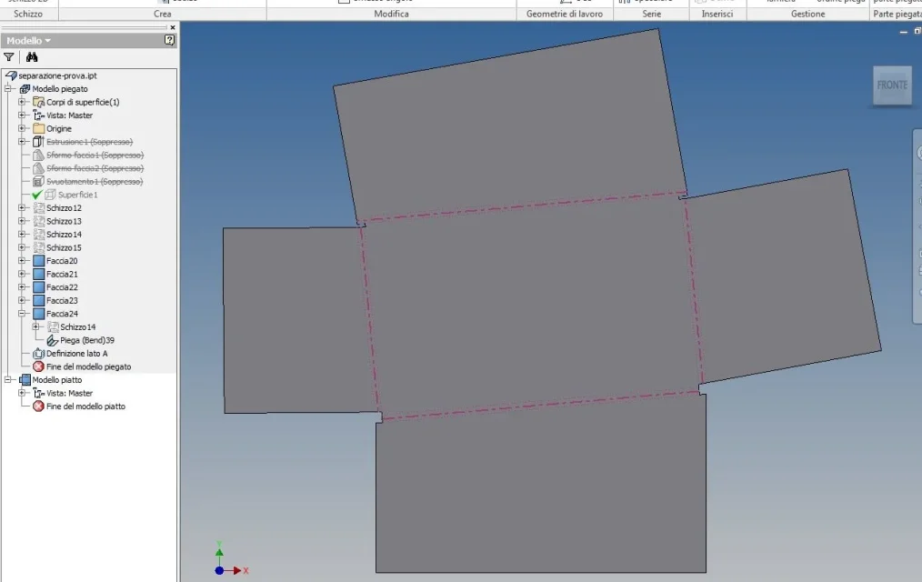
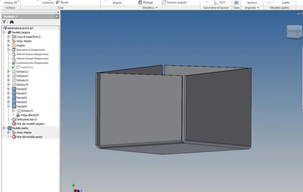
in the attached image there is the piece until I managed to arrive (i.e. before using the command "piega (bend)" which fails).
I hope I could explain myself, but I'm here.
Thank you for your help. :smile:

I am trying to make a sheet metal box with the bottom tilted in two different directions, one according to the x axis and the other according to the z axis, serving me of the respective side edges or banks as a reference, than which, the two sides of the sheet must be tilted.
the box is located at the beginning of a conveyor belt, and the two inclinations serve to ensure that the objects that are inside, converge all towards the exit opening that is located in the lower corner of the four sides (in practice the pieces go down by gravity thanks to the sloped bottom on two floors, xz and xy).
I wanted to try to do it first as solid and then convert it into sheet metal, and in fact the solid I made it as I wanted.
the problem arises when converting it into sheet metal; as first step I extrude the rectangle which will be the base of the box and then I deform the bottom according to the two directions.
the emptied holding the thickness of 1 mm, and lastly convert it into sheet metal.
done this, as next step, with the fold command (bend), select the outer edges of the bottom, one by one, to transform them into folds, and the problem is precisely this: once selected the lower edge of the box (the long or short side are indifferent), I appear the preview of the fold, but then when I confirm with ok, it gives me error and does not, and the message is this: "No corresponding face has been found."
I press that if the bottom is straight, then with the corners at 90°, the command works fine and converts me into fold all the edges of the box, bottom and walls.
in practice is the inclined bottom that gives him problems.
I point out that the piece I tried to achieve with solidedge following basically the same procedure (of course the commands are slightly different in the name, but the result is the same) and I did not have any problems, it seems strange to me that with inventor (which is the software with which I am more comfortable) I must meet these difficulties.
I'm probably wrong with something, and I just wanted to ask for your help to help me realize it.
in the attached image there is the piece until I managed to arrive (i.e. before using the command "piega (bend)" which fails).
I hope I could explain myself, but I'm here.
Thank you for your help. :smile: