folle76
Guest
Hello.
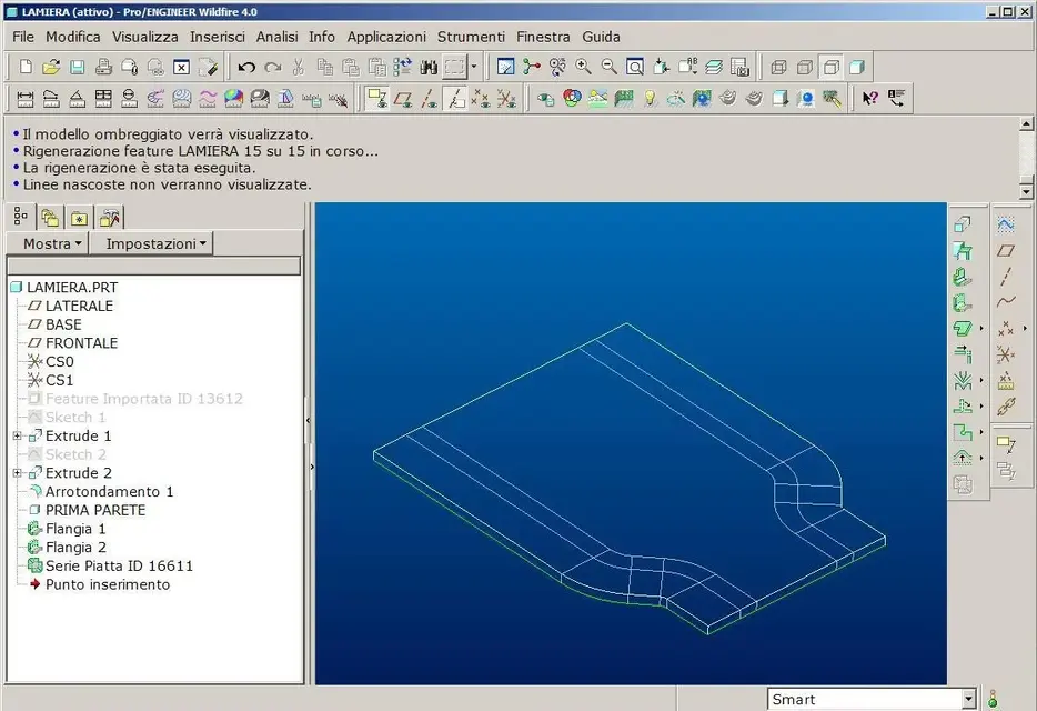
provided that of proe something I understand, but of sheet metal processing technology are totally fasting, how can I create a piece as an attachment (.iges, .prt (wf 5)) so that it is obtainable by bending? so as is the flattening feature I fail.
Thank you.
provided that of proe something I understand, but of sheet metal processing technology are totally fasting, how can I create a piece as an attachment (.iges, .prt (wf 5)) so that it is obtainable by bending? so as is the flattening feature I fail.
Thank you.