LC23
Guest
Hello everyone
I have, together with two other boys, the task of simulating the design of some components.
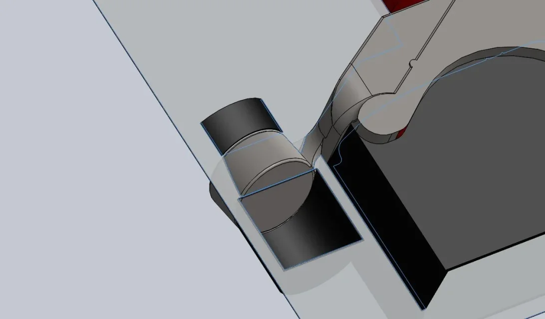
The axieme is the left rear wheel support of an alpha 147 comprising the hub, to be worked on the mud and the hub support, to be produced by fusion, using the method of the shell molding.
In the annex I have left the piece, do not criticize me, please, the mode of modeling of the same because I did not do it, and I would like to avoid doing it (of course) ... try to make what we have")
I've been trying to find solutions for a long time, I can't get my head off.
I can't imagine the model plates, I don't know how to divide the piece, I don't know if you should use inserts.
the first problem is the inclined eyelet that presents subsquadri in almost all the solutions that come to mind.
the second is that the model plates are usually flats and division plans are used, while I think it is appropriate to develop a division surface here but.... how?
The third problem, unfortunately not solved before the first two I believe, is : how can the casting channel and materozze? ? ?
hoping not to look like a scanty fatigue (even because I really can't, from several weeks, figure out how to do it I'm piece)
I ask you directly, can any of you tell me how you usually do such a piece with this technique?
Thank you.
I have, together with two other boys, the task of simulating the design of some components.
The axieme is the left rear wheel support of an alpha 147 comprising the hub, to be worked on the mud and the hub support, to be produced by fusion, using the method of the shell molding.
In the annex I have left the piece, do not criticize me, please, the mode of modeling of the same because I did not do it, and I would like to avoid doing it (of course) ... try to make what we have
I've been trying to find solutions for a long time, I can't get my head off.
I can't imagine the model plates, I don't know how to divide the piece, I don't know if you should use inserts.
the first problem is the inclined eyelet that presents subsquadri in almost all the solutions that come to mind.
the second is that the model plates are usually flats and division plans are used, while I think it is appropriate to develop a division surface here but.... how?
The third problem, unfortunately not solved before the first two I believe, is : how can the casting channel and materozze? ? ?
hoping not to look like a scanty fatigue (even because I really can't, from several weeks, figure out how to do it I'm piece)
I ask you directly, can any of you tell me how you usually do such a piece with this technique?
Thank you.