• This forum is the machine-generated translation of www.cad3d.it/forum1 - the Italian design community. Several terms are not translated correctly.

simplify series of machining

  • Thread starter Thread starter davide75
  • Start date Start date

davide75

Guest
Hey, guys, we're dealing with this guy's problem here.
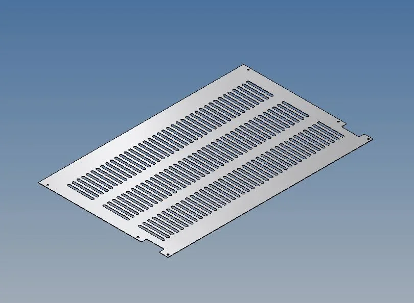
we have been asked to carry out all the cards with asolate sheet ( attach photo) for all groups that make up my machine/plant. the problem is that with models of this type inventor (I use 2016 ) nails as my plant increases.
we are looking for a way to simplify the sheet metal model (maybe showing only the first two rows of asole ) but without results.
in the part there is no possibility to make levels of view or detail. derivative components are trying because we have to see how our pdm behaves during duplication/management. drawing in the table and not in the model becomes honorable.

ideas?

inventor 2017 solves this "problem"
 

Attachments

  • Cattura.webp
    Cattura.webp
    48.9 KB · Views: 10
I have the same problem, direct solutions I have not found: as I use the "simplified contour" by closing all the holes, and these sunburns disappear.

there is also the possibility to make grills only in the flat model: I wouldn't do it (for personal tastes) but maybe you like it.. .
 
I try...
the series, is it a set of sunshades in sketch, or a series of processing of a first cut of a single asola? because it changes a lot... It is less expensive to calculate a series of machining than a series of geometry in one sketch.

in the second hypothesis (working series), did you try to "play" with the calculation options of the instances of the series?
 
I try...
the series, is it a set of sunshades in sketch, or a series of processing of a first cut of a single asola? because it changes a lot... It is less expensive to calculate a series of machining than a series of geometry in one sketch.

in the second hypothesis (working series), did you try to "play" with the calculation options of the instances of the series?
already made ilario in both ways. we also tried to make the series directly inside the sketch but there is to become skewers in the editing phase and however in both ways you do not notice eating in the main axieme.
it would take a kind of view level where I can simplify or delete the display of the series so as to mount it in the axieme.
 
it came to mind to try to pierce the file as an ipart where we create a line by eliminating the series
 
as not said. you mess with the pdm because it sees as many files as the lines of the ipart
 
But when you do the replacement and you have to do the table?
Well, having the replacement doesn't change anything, depends on what you have to do/get: you can exchange between original model and simplified contour at any time. what I do is to make a completely modeled machine and then use in lay-out or general assembly the levels of detail with replaced parts, the boards of general assembly are good also with the simplified parts. with the levels of detail you can make all the complete/simplified model mix you want.. .

I hope I explained. Anyway, it doesn't solve the problem, it's just bypassing it.
 
I think it's slow. I have never tried, however, to make a set of sketch points and then use a sheet punch to generate the wounds all at once: Until now I've serialized cuts.
 
but the simplified replacement should be a good solution... at the end is nothing but an extra file. together create two (or more) configurations (a complete and the "read" that serve) with the simplified parts and then at the table choose what to display.
a function that I have used lately (especially to simplify sub-assiemi) and has solved a bit of "heavyness". . .
 
with the substitute we have problems with the pdm as it is necessary to create a double code and therefore in the separate of the main axieme comes the substitute
 
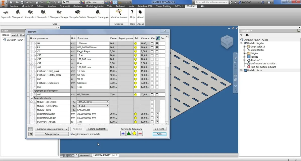
so much to list everything that comes to mind: processing is possible to be suppressed according to the value of parameters (dx on processing > properties). yes it can import a value "surface = 1su" in all grids, taking it from one side or from a excel sheet, making the suppression settings on the various series and, changing a single value, suppressing/enable everything on all pieces.

or do an ilogic rule that does the same thing...
 
Okay, just that if we stop, I'll help you, but when I go to the table, I have to reactivate the work and so we're all over again. I tried to make a joint with the inside of the work together and see if they could be handled with the levels of detail, but nothing because they are not recognized as such.
making iparts create me as many rows so I have to put in the pdm as many codes as the rows because each row generates a different solid and then my pdm needs it to be coded to manage it
the substitute works together.
I would need something to manage the work of the part at the level of view so that I can manage a single part with visual representations, which at the moment possible only together. If I had the managed part in this way it would be easier to manage the parts at the level of assembly and in the table then I can choose how to view it.
I don't know if I explained
 
I hope I understand your problem... and above all to solve it

I thought about this:

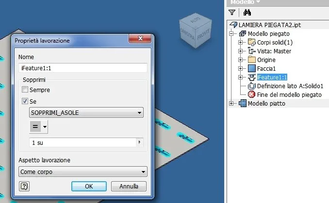
each sheet has in fx parameters a user parameter: example "sopprimi_asole" without unit (on) set to 0_foto__029.webpalways in each sheet, making dx key on the punch series, select properties and activate the option :
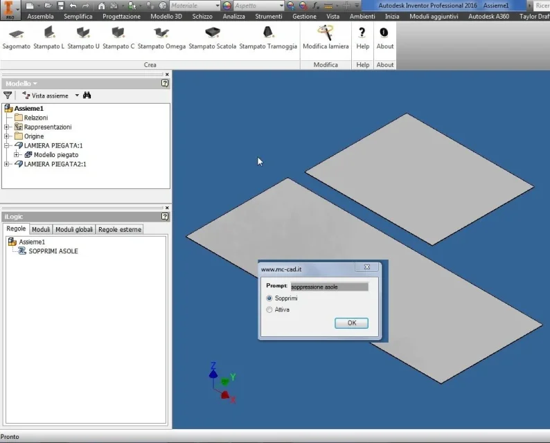
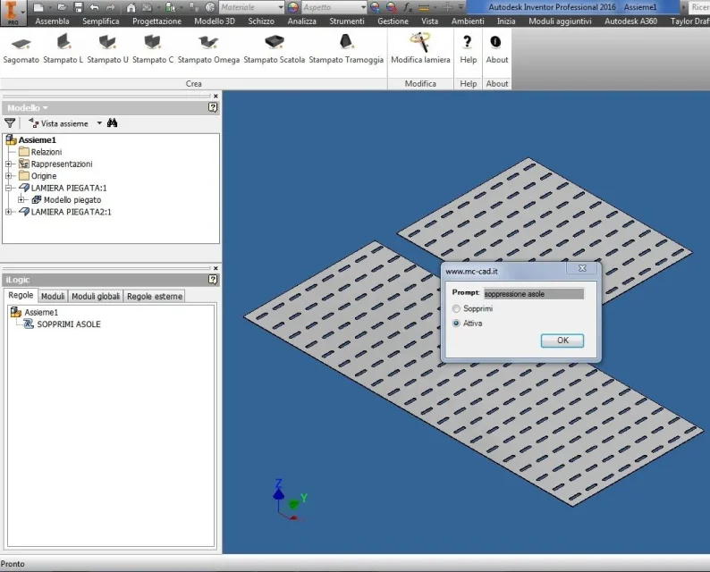
Stop me if "sopprimi_asole" = 1_foto__030.webpto activate or suppress all sunflowers at the same time within the axieme, I created an ilogic control that, launched by the axieme asks if you want all active or suppressed suns
via the button automatically turns on or off all the sunbeds.
ilogic command
I hope I've been helpful
Hi.
sopprimi.webpattiva.webp
 

Attachments

Thank you! I'll be right back tomorrow. but the doubt that it ascends to me now is: at the level of putting on the table referred to the part how it behaves? In the sense, in combination Ilogic command launch, we suppress the sunflowers ok, but if I open the model what makes me see?? the exact model or the simplified one? I also saw that you created the asola as a punch, but in case the weave created with the classic sheet cutting command (i.e. I do the sketch of the asola and then cut ) is the same your method?
 
si, vale the same also with the cut, you will have to activate the suppression on the cut and not on the punch
for tables of course if deleted, they will not be displayed; but at least you will have "light" assemblies creating that simplified representation effect that, currently there is not in the parts.
to make the tables "read" you can always create views in raster mode (so they will be read) and update them only at the end of work.
ps. if you need clarification on the punches, in previous post I made available a pdf on the creation and management of the punzoni and families of punzoni
hi and good work
 
Hello, thank you for the answer. This morning we try to see if with your command we can do detail levels so that by opening the model I can see it complete and not simplified for the question of putting into the table. I know. Thank you
 

Forum statistics

Threads
44,997
Messages
339,767
Members
4
Latest member
ibt

Members online

No members online now.
Back
Top