• This forum is the machine-generated translation of www.cad3d.it/forum1 - the Italian design community. Several terms are not translated correctly.

size rack

  • Thread starter Thread starter Gio_RS
  • Start date Start date
I attach the photo of a lazy helical mechanism rack (not of the servosterzo that I am studying) and it seems to understand that the teeth is straight but likely inclined to the angle of inclination of the propeller of the pinion....you want what do you think? ?
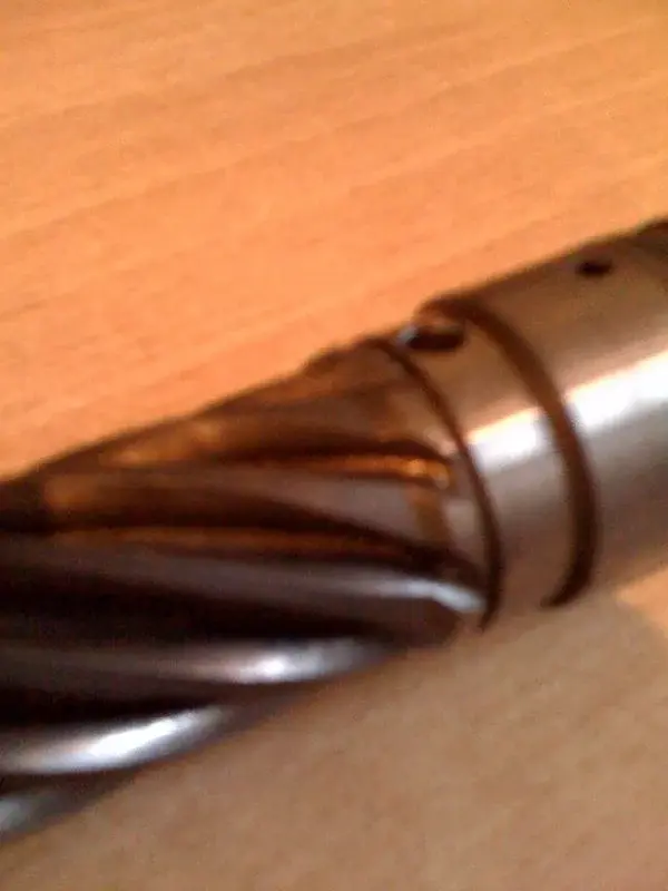
here is what I told you in the previous post: helical with helical, straight with straight...
 
I use the sp0 version of 2009, if you do not have at least this you cannot view them. . .

for sampom....when you refer to the swep of the teeth you talk about the rack if I understand well and should create a profile of the normal tooth to the sketch guide, which use for the swep....you refer to this and not to the swep of the shirt (rocchetto)right?? ......instead of how you rightly said couplings of straight/right teeth allow the exchange of motion between parallel axes, while helical/helical teeth allow transmissions between orthogonal planes or sghembi, especially orthogonal axes when the angle of the helix of the two teeth is the same..... now I wonder but if the angle that I follow to obtain the ? ?
 
a pair of gears, even in your case are a rack is a toothed wheel of infinite radius, must correspond with module, and inclination of the propeller to gear.
you can't make a helical toothed sprocket with a straight teeth rack... .
In fact, we've been trying to tell her:biggrin:
if the pinion has the propeller dx the rack must have the propeller sx and vice versa.. . .
Well, not necessarily. this applies to parallel axes and skewers, for the orthogonals the verse of the propeller is the same.
in case yes, the verses are opposite.

greetings
Mar
 
for sampom....when you refer to the swep of the teeth you talk about the rack if I understand well and should create a profile of the normal tooth to the sketch guide, which use for the swep....you refer to this and not to the swep of the shirt (rocchetto)right?? ......instead of how you rightly said couplings of straight/right teeth allow the exchange of motion between parallel axes, while helical/helical teeth allow transmissions between orthogonal planes or sghembi, especially orthogonal axes when the angle of the propeller of the two teeth is the same.....

Yes, of the rack but also of the pinion. tooth sketch should be normal to extrusion path (used for construction "normal plane to the curve" e seleziona set origin on the curve. touches with the pointer the sketch of the propeller and its initial point).

you have not read well that dispensation that I have posted just above:cool::smile:.
even with the helicals you can transmit motion between parallel axes, and it is not said that for the orthogonals the angle of the helix should be the same (as I said above are the verses that change, and the resulting "accident" angle is given by the algebraic sum of the angles of the two teeth)
Now I wonder, but if the angle I follow to get the teeth on the rack is not equal to that of the propeller of the rocchetto (magari is smaller) it is possible to place the rocchetto with a non orthogonal axis to the rack and allow the transmission between axes not more normal? ? ?
Of course, we speak in fact of sghembi axes (see above to get the resulting angle).

greetings
Mar
 
In fact, we've been trying to tell her:biggrin:


Well, not necessarily. this applies to parallel axes and skewers, for the orthogonals the verse of the propeller is the same.
in case yes, the verses are opposite.

greetings
Mar
Yeah, sure.


q8

I referred to the specific case....

Hello, beppe
 
I did some tests..:rolleyes:. .Effectively the profile is different much better.... now this thing you said made me reflect an aptitude, looking in fact the grooves (on the helical toothing), released from the tool, I noticed that it decreases in depth evenly until I see the diameter value of the shirt(n know if I managed to explain myself with a photo maybe you understand better). Now in this way I get an uneven compartment like the real one.
I should look for another solution.... I thought of a single loft cut in which I gave the curve to evolve and the two sections, one faithful to the tooth compartment and the other also, but they postpone it to a greater radial distance so as to obtain a more uniform compartment. I think it's a good solution, or would you recommend another road... .
 

Attachments

  • foto(12).webp
    foto(12).webp
    32.9 KB · Views: 8
I did some tests..:rolleyes:. .Effectively the profile is different much better.... now this thing you said made me reflect an aptitude, looking in fact the grooves (on the helical toothing), released from the tool, I noticed that it decreases in depth evenly until I see the diameter value of the shirt(n know if I managed to explain myself with a photo maybe you understand better). Now in this way I get an uneven compartment like the real one.
I should look for another solution.... I thought of a single loft cut in which I gave the curve to evolve and the two sections, one faithful to the tooth compartment and the other also, but they postpone it to a greater radial distance so as to obtain a more uniform compartment. I think it's a good solution, or would you recommend another road... .
what goes to represent the exit of the creator on the dense tree piece I realize it with a somewhat long process to explain. . . .

use the surfaces.. .

first a cut with sweep of the solid body using as sketch the profile of the tooth compartment.

then from there I go to utlize the surface command bar which then allows me to cut the solid so as to represent similarly to the cutting of the creator the tooth compartment.

the description is a little long, but as soon as I get back to work, now I'm in vacation I create an instruction file and the place...

for now I believe that at the level of visual solution your can be ok!! !

Hi.
 
This command you talk about,relative to the surfaces I never used it.....it would be nice to see something about it, I thank you already in departure for the file....the road I chose nn is bad, the visual resulate is very similar to the real one...but it is a solution that I do not recommend to many, it took two days to realize the loft cut,it was a very long job: eek: eek: .

Hello, yo
 
creation output creator for pinion with helical toothing

1-function merge surfaces: click on the tooth surface and then hide the solid body of the teeth

2-create plan: - extreme point tooth crest
- helicoidal ridge line

3-extend surface: extend the tooth profile to the created floor

4-convert tooth profile sketch on created plane

5-unite with a construction line the 2 vertices of the tooth profile sketch (converted to point 4)

6-Insert a point (scratch) at the average point of the line created at point 5

7- create a mid-range line and place it at the intermediate point (see point 6) perpendicular to the line created at point 5

8- create a perpendicular line to that of point 7 and place it at the end of the same (rotation axis for cutting with creator)

9-create a surface revolution

10-uniting the 2 surfaces (bridge surfaces and revolution surface)

11- reactivate the solid body

12- perform surface cutting with the sup created at point 10

here the tooth cut more similar to that actually performed by a creator in the workshop.

I hope I've been helpful

Hi.
 

Forum statistics

Threads
44,997
Messages
339,767
Members
4
Latest member
ibt

Members online

No members online now.
Back
Top