• This forum is the machine-generated translation of www.cad3d.it/forum1 - the Italian design community. Several terms are not translated correctly.

sizing tubes ventures

  • Thread starter Thread starter mambo1988
  • Start date Start date
bhe, if you put an output tube your pressure at point 2 (exit from the venturi) is no longer 1 bar absolute (atmospheric pressure) but 1+x, given by the load losses of the fluid in the "unload" tube.
This makes all working conditions change, of course.
 
exists any way to quantize the loss, knowing section length and material of the pipe? I also considered the bernol equation between the input and the narrow section (where I imposed a lower pressure than the atmospheric pressure) and did not consider the tube to be connected later :
 
exists any way to quantize the loss, knowing section length and material of the pipe? I also considered the bernol equation between the input and the narrow section (where I imposed a lower pressure than the atmospheric pressure) and did not consider the tube to be connected later :
not by chance the venturi always puts in the terminal part of the plant

Load losses are two types:
- continuous
- localized

to define continuous losses you need to "identify" the type of motorcycle (laminating or turbulent. ..transition let us lose).
to define the localized load losses you need the geometry of the discontinuity and speed of the fluid.

I had made a spreadsheet that defined load losses (distributed and concentrated) in a plant (which you could obviously configure by choosing different options).
If I find you the place.

At the moment I'll coach you this:
 

Attachments

This afternoon I will study load losses.
If I can quantize it will be possible to insert this venturi 1 meter before the exit? ?
(I remember that we are talking about 2-3 bar input pressure which uses as a steam fluid)

p.s thanks for the answers
 
This afternoon I will study load losses.
If I can quantize it will be possible to insert this venturi 1 meter before the exit? ?
(I remember that we are talking about 2-3 bar input pressure which uses as a steam fluid)

p.s thanks for the answers
Yes.

However, you must define load losses well and recalculate all new working conditions.
 
interesting the discourse of load losses, I am studying technical physics (among others I have the examination), being steam in a section tube(4 mm) the bike we can consider it completely developed (i.e. consider the input speed before it enters the tube). ..that I in practice should find the force necessary to move the air into the tube (about 1m) after the venturi tube (knowing the friction of the rubber, density, viscosity air).
I hope I'll come over with it!
 
attention: completely developed motion means that the speed profile does not vary along the axis of the tube, contrary to what happens in the input region: The latter considers it at least 10/15 diameters if the regime is turbulent (re > 2000/3000) and 0.05*re long if the flow is laminar (re = ud/v, u speed "media", of internal diameter, v cinematic viscosity). the speed is "average" because the speed profile varies from the axis of the tube to the wall, and is considered as an average not that of input but that given by the expression of the mass flow m: u = m/(rho*a), with section of the duct and rho density. as you see, for a steam or gas much more than for a liquid, the density would decrease along the axis of the pipe (because the pressure decreases due to the pdc), causing an increase of the speed to maintain the mass flow in a constant section tube (condition of continuity, which must always be respected). for a maximum account, consider the constant density. normally, in everyday problems usually the entry region is neglected: in your case would be a few cm...

So, returning to your problem, I would do a nice xls sheet where for different speeds of steam (say 5, 10, 15....m/s) I would calculate the number of reynolds. for each point I would evaluate if the flow is laminating or turbulent (you can use 2500 as a "displacement"). if it is laminar, the friction coefficient does not depend on the roughness of the tube and is worth f=64/re. if instead it is turbulent, it also depends on the relative scabness of the tube: I would consider it equal to surface roughness/internal diameter. the first you find it in the tube datasheet, otherwise you take 0.05 mm for a new steel tube. at this point you find f knowing relative scabrezza and king using the moody diagram (see google) or an empirical formula like colebrook/white (google again!).
at this point the pdc distributed for incomprehensible fluid you calculations as

dp = 0,5*rho*f*(l/d)*u^2 , with tube length

said this, there are very good free or relatively low network programs that allow you to calculate pdc for many geometries with many different types of fluids: for example http://www.pressure-drop.com/...and there are also nomograms for the calculation of pdc distributed with steam.

But... it's not over! this is an account for a hose without "accidentity", i.e. curves, enlargements, shrinkages, valves...which constitute load losses concentrate Right.

These are typically calculated as dp = 0.5*c*u^2 with c concentrated load loss coefficient: search on google, c depends on the geometry of blindness. if you are talking about valves or other components, you never find this coefficient in the datasheet of the builders but the so-called "kv", experimental value that is equivalent to the reach of a reference fluid (usually water) to a certain temperature (declared) with the deltap of a bar. From this through transformations that take into account the fluid actually used you can trace to the deltap given a certain flow: on the catalogs of the builders is however reported all the (simple) procedure so I recommend you read them directly if you have a problem with the kv.
Considering therefore in your xls all the pdc (including the expansion on the output section that turns pressure into speed) and imposing on the output section 1 atm you should get the pressure upstream of your tube to vary the speed (port)!
 
I thank all for the answers, I have just finished all the tests, now I can devote myself exclusively to the thesis, and I would like to make this device work.
by summing up the "tubo venturi" realized, it only works if placed towards the end of the circuit, instead this effect fades if we put the venturi tube inside the circuit (after the "venturi" we have at the exit we no longer have the atmospheric pressure, but there is a rubber tube of about one meter with a diameter of 4mm, which will cause resistance to the passage of steam, and therefore the steam will prefer ?
 
bhe, if you put an output tube your pressure at point 2 (exit from the venturi) is no longer 1 bar absolute (atmospheric pressure) but 1+x, given by the load losses of the fluid in the "unload" tube.
This makes all working conditions change, of course.
in fact this is the problem... .
 
Isn't that you could post a detailed circuit diagram?
I think it's the cleaner's duct that has excessive load losses.
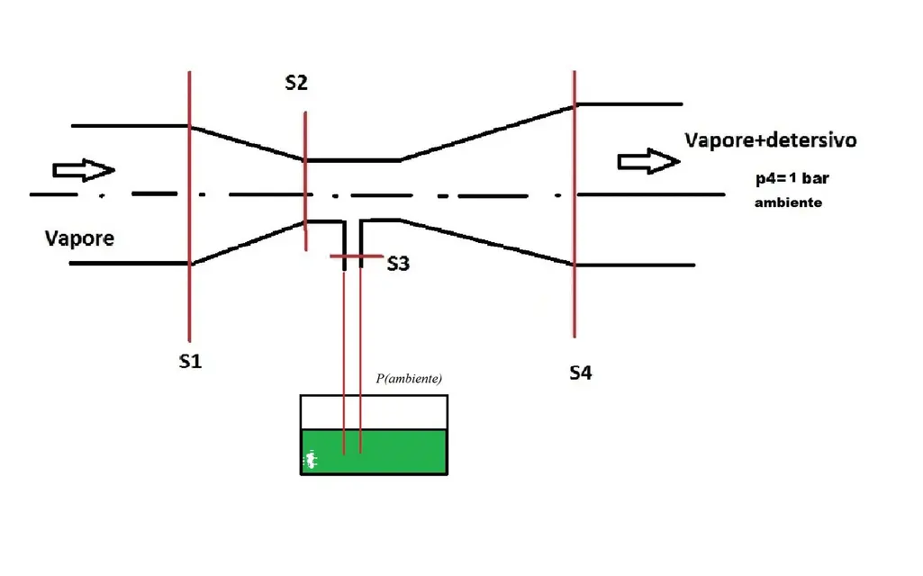
This is the pattern of the venturi tube.
It must be connected, between the steam generator and the output, I explain better.
we have g.v then rubber tube,we collect the venturi, and then again a meter of rubber tube.

the problem is that I have dimensioned(wrong) all considering the pressure atm, as exit from the venturi tube, instead I realized that the force that exerts the steam on the walls of the tube is "high" (yet quantum the losses) to let the steam out inside the tub of detergent......

if placed in front of the lance, the system works well, the problem is to insert it inside the circuit.
 

Attachments

  • TuboDet.webp
    TuboDet.webp
    34.3 KB · Views: 8
This is the pattern of the venturi tube.
It must be connected, between the steam generator and the output, I explain better.
we have g.v then rubber tube,we collect the venturi, and then again a meter of rubber tube.

the problem is that I have dimensioned(wrong) all considering the pressure atm, as exit from the venturi tube, instead I realized that the force that exerts the steam on the walls of the tube is "high" (yet quantum the losses) to let the steam out inside the tub of detergent......

if placed in front of the lance, the system works well, the problem is to insert it inside the circuit.
I press that I didn't read your post, but I'm only responding impulseally to what I saw.
Why do you put the cleaner's tank down? Do you know that if you put it on top, make it easy?


edit:
Do you have a way to detect the pressure?
 
I press that I didn't read your post, but I'm only responding impulseally to what I saw.
Why do you put the cleaner's tank down? Do you know that if you put it on top, make it easy?
Yes, I know, this is only one scheme!! what I want to tell you is that in the restricted section there is no depression, because the rubber tube I collect after creates a certain "pressure due to friction", so the steam prefers to go out where the tank is... .

I did several tests, I also thought of putting a closed tank, so as to put it in pressure, the system would work so but then I would have other types of problems... .

how does a venturi tube be sized that does not have p=1 bar at the exit?? but 1+x...
 
Yes, I know, this is only one scheme!! what I want to tell you is that in the restricted section there is no depression, because the rubber tube I collect after creates a certain "pressure due to friction", so the steam prefers to go out where the tank is... .

I did several tests, I also thought of putting a closed tank, so as to put it in pressure, the system would work so but then I would have other types of problems... .

how does a venturi tube be sized that does not have p=1 bar at the exit?? but 1+x...
Wait wait for me to have a doubt:
but you, in your scheme, predicted by chance a fantastic Non-return valve?
 
Wait wait for me to have a doubt:
but you, in your scheme, predicted by chance a fantastic Non-return valve?
mhhhh.... no I just thought of putting a faucet, to adjust the flow of detergent that I should in theory aspire to
 
mhhhh.... no I just thought of putting a faucet, to adjust the flow of detergent that I should in theory aspire to
as lino banfi says: "disgraceful"!:tongue::biggrin: (in joked tone of course, as you see from the faces).
You can use a simple ball valve with spring... and you can self-build it.


good instead to put the regulator.
 
ahhahaha "moment", 2 questions:
-but this valve(not knowing how it works) causes me a load loss to make it work? ? ?

-The convergent-divergent is important, how can I resize it considering that at the exit I no longer have 1 bar?? ?
 
ahhahaha "moment", 2 questions:
-but this valve(not knowing how it works) causes me a load loss to make it work? ? ?
Yes, but it is irresponsible because you have to win only a few grams of precarious.
Have you ever seen a vn?

-The convergent-divergent is important, how can I resize it considering that at the exit I no longer have 1 bar?? ?
I don't want to say but I'm beginning to doubt the speech I made you about the downstream load losses (my fault!:tongue:). load losses on the cleaner's duct are fundamental.
some doubt that creeps into my mind leads me to remember that who "command" is the variation of the fluid speed in the convergent-divergent.

definitely, introducing the vn, the system will work. not as before because you introduced an extra load loss...but still it will return to work.

Anyway, if I can, I can put two accounts down... I'm convinced that the outgoing pressure doesn't come into play.
 
Yes, but it is irresponsible because you have to win only a few grams of precarious.
Have you ever seen a vn?

I've never seen her, I'll get a study, and then I'll let you know.
yes this, xò in theory the tube placed at the venturi exit having a diameter of 4mm, and being of rubber will cause friction that results in a loss of load, and makes the steam come back and prefer to pass for the reservoir (at least in part)....
When you return to the vn, you say that by putting it after the divergent system could work?(i.e., the steam does not return to the cleaner)

However, I have to put the rubber tube after the venturi tube... I will never come out of it:confused:
 

Forum statistics

Threads
44,997
Messages
339,767
Members
4
Latest member
ibt

Members online

No members online now.
Back
Top