• This forum is the machine-generated translation of www.cad3d.it/forum1 - the Italian design community. Several terms are not translated correctly.

sketch bend

  • Thread starter Thread starter Fabioelle
  • Start date Start date

Fabioelle

Guest
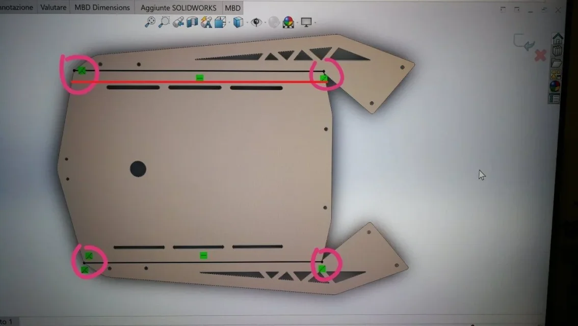
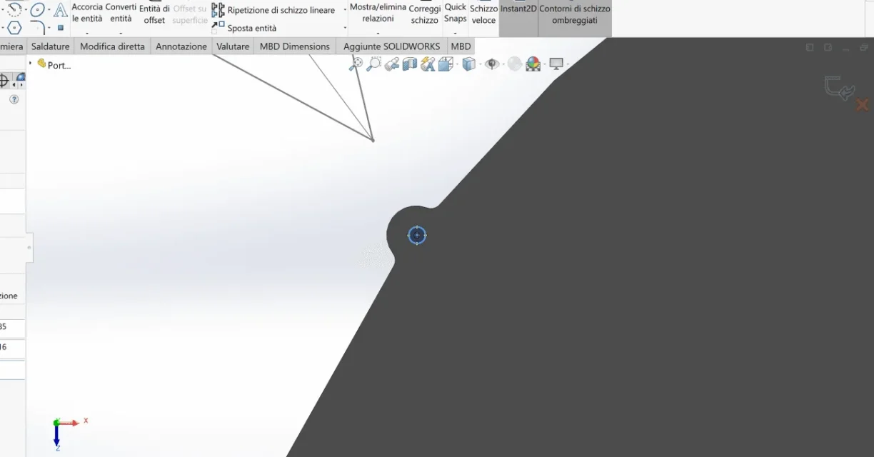
Hello to all I have a problem to bend a flat sheet using the fold function of sketch, as from photo I draw the fold line but nothing happens, if instead I extend the line to the right wing bend it but to me it serves that part stays healthy and not split from the fold. I hope to have been clear, thanks to those who will help meIMG_20200522_200746.webp
 
specify and attach :
Solid version (to be added to profile)
files not to invent geometries of nose
I need that part to remain healthy and not split from the fold
What does that mean?
If you bend a leg you take the right side, it is inevitable.
sketch lines should not cover all length, but only mark the fold area therefore theoretically it would be enough to make a 1mm long line.
 
2020 version,
I'm sorry for the sketch, but I don't have a file at hand. I understand what you mean, even a small line bends throughout the length, so you belong to draw it hand in 3d, there is no way to bend it like this? IMG_20200523_195703.webpIMG_20200522_200746.webp
 
so to the eye, by maximizing the image, going for inspiration and entrusting me to the magicbula it seems to me that there is no drain where there is the right wing so rightly can not make a fold without involving the aletta.
as a worker I imagine you will know how the bending of sheet metal works.. .
 
I know, and the discharge is even if you don't see in the photo... to understand it I would fold by getting the matrix where I drew the red circle so as not to bend the rest on the right, but I'm not finding a way to do it on the pc?... thanks the same
 
I'm not finding a way to do it on the PC
so you have the file available.
Why don't you train him?
Why don't you write the solid version in the profile?

If you want also a step I can give us an eye today, otherwise wait tomorrow or some other user passing through
 
Hi, it depends a lot on how you modeled it, but this definitely already you know.
as you want to bend it is very clear.
I think you could shape the solid without the two appendixes you want to keep flat, apply the folds then extrude and fill the appendix as you need.
Bye.
 
depends a lot on how you modeled it, but you definitely already know it.
if he knew he would attach the file as he was asked
I think you could shape the solid without the two appendixes you want to keep flat, apply the folds then extrude and fill the appendix as you need.
could also model with flange functions of the edge, then already folded, stretch it, make cuts and decorations and then fold it; The methods for modeling it are different, but they don't need to fall where it's wrong now.
 
error is clear, an account is an operation that you can do physically on the machine in the bending phase, as described by him i.e. fold with flap out prisma, an account is how the software was compiled to perform that operation that does not take into account this fold strategy. In my opinion it may be considered a programming error even if one thing does not do it as you want (solidworks or inventor that it is ) you wield and you get it done to him, to scream if it serves.. .
In summary as I wrote, solid or inventor, that operation fails to manage it so, as he intuited, he must shape the piece as the software wants. the sitema does not admit derogations. Good Sunday to all. Hi.
 
it may depend on the size of the discharge that he says to be there, but that even by enlarging the image you do not see well; if so it would not be a limit of the program, but of the modeler
the discharge also in the productive reality is necessary to be able to carry out the fold without deforming the sheet.
 
but the discharge decides it by software, so if it depends on that it has to do tests with different dimensions (and here it depends on the modeler ) even if I think that often plan b is an excellent solution, we raise the problem and so.
 
thanks to all of the answers, I realized that you can definitely reach the problem but I have not so much experience on solidworks, I have passed this dwg file designed on autocad (together with others) and imported them on solidworks to make a set. as soon as I can attach the file if you want to help me, thanks again
 
here is the file
update: if I draw the fold line a few extra cm towards the center, it can bend. in the file I inserted arrows indicating the ends of the fold line.. Thank you.
 

Attachments

If for a few centimeters (orror, in mechanics the millimeters are used) you mean where the red line is, it is obvious that you bend it, there are no forms of contour.
I am convinced that it is an exhaust problem on the corner that is probably too small
 

Attachments

  • IMG_20200522_200746.webp
    IMG_20200522_200746.webp
    42.5 KB · Views: 9
does not charge me the step ne ap203 ne ap214 file, however I am seeing that the discharge is 0.5 mm maybe this is the problem
 

Attachments

  • Immagine.webp
    Immagine.webp
    30.8 KB · Views: 10
  • Immagine2.webp
    Immagine2.webp
    26.5 KB · Views: 7
the width is fine, but it must pass the fold line according to the fold radius.
the line in that area is not good because it folds the tip of the flap
Image 2 doesn't understand what it is.
to attach a step buy it exactly like solid file
 

Forum statistics

Threads
44,997
Messages
339,767
Members
4
Latest member
ibt

Members online

No members online now.
Back
Top