• This forum is the machine-generated translation of www.cad3d.it/forum1 - the Italian design community. Several terms are not translated correctly.

sld reverse

  • Thread starter Thread starter Gio_S
  • Start date Start date

Gio_S

Guest
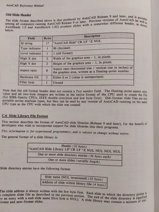
Good morning to all, yesterday, as I usually do, instead of with the week enigmistic I devoted myself to my favorite puzzle with the analysis of the coding of graphic formats.
the file type sld is not document, or better I do not find it, and I am at the very first pass.
It's a vector file.
- has a header (in fact incorrect to call it so because as a whole that I isolated as a repetitive it certainly contains info on the graphic system in use), but a certain fact is that the plotting, attention, in my elementary case of lines to be traced with which I started, begins to byte 34°
- then I find 2 byte(short) + 2 bytes per x,y of departure (with origin 0.0 low left), with 4 hexadecimals per axis, to be read from the last.
- then, consecutively, another 2 bytes + 2 bytes for x,y end line
- then two bytes detachment from the next line (color? for now I don't know)
Actually, I don't even know if they pull the pen or they say it goes on. for now I analyze two separate lines.
- Finally 2 bytes per fine file.

It seems quite elementary to build. I will make us a small bitmap vectorizer, like what I use for my works, which transforms pixel lines into solid color (small packages cad optimized by 16 million)
that I need for my scanning work photos trains for 3d printing purposes, slds for now are just like fun, maybe I will need to correct the menus starting from bmp.
If by chance someone had more information on the format coding thank you!
 
Meanwhile I solved black and white... then I will study the colors!
I don't know if you see it or just work on my system
 

Attachments

here we are with the first version, tested in various ways. I have implemented for now only a few basic autocad colors, but it is easy to add others, if in the meantime in the bitmap does not find a certain color, it returns it in medium gray (9).
Code:
If you're not
drw=1 'red
elseif col=65280 then
drw=3 'green
elseif col=16711680
drw=5
♪
drw=7 black
elseif col=16777215 then 'transparent white background in the sld
drw=-1 'to start there is no color, it is only a flag
♪
drw=9 'all the rest is gray
end if
I don't put the executable, I don't want stories with all the viruses around, and I'm sure that win would block it.
I put the source in rapidq, which is a powerful and simple basic, and that is the language I know perhaps better. you fill in the old way, unique row without bales or bookcases nor includes various, there is already inside from the wheel, with calls to bees of win. but if one has practicum can rewrite it as you want, remove file management, the routine that writes the slide scanning the bmp is short and simple (sub exportsld), and is the heart of the program
Sure he'll have some mistakes but I haven't found any.. This in picture is my stress-test.
No. the size of the bitmap must be that required 588x588
internal.sld is the one generated in the example
 

Attachments

  • Clipboard01.webp
    Clipboard01.webp
    11.2 KB · Views: 17
  • slide.zip
    slide.zip
    32.3 KB · Views: 2
already version 00.02
correct overexisting cycles (inoffensive)
but also bugs (when a carrier ended up against the right limit I did not finish it).
I hope not to do as ms that updates every day and as system a foul opens another one.. .
 

Attachments

I wanted to answer your first message first, but then some commitments distracted me. . .
I don't know if you still need the coding of sld files (I think not)... anyway the allego (prese dal manual i auticad 10)
 

Attachments

  • sld1.webp
    sld1.webp
    180.8 KB · Views: 13
  • sld2.webp
    sld2.webp
    176.9 KB · Views: 11
  • sld3.webp
    sld3.webp
    172.9 KB · Views: 7
Many thanks, I need yes, on the header I had gone nose maintaining fixed dimensions certain values, like the maximum dims of my screen, as well as mslide coding!
Thank you!
 
hello to all, I have submitted the program to believe every test, without generating errors.
I personally find it useful, can actually manage each image.
I am preparing a "template" bitmap to use as a double valence rgb palette, with the rgb definition flanked visibly and exactly to the basic colors of autocad.
For example, the red "pure", commonly coded 255,0,0, in autocad is number 1.
use the template palette is important because it will contain "pure" colors, and therefore for example a 255,1,1 color non will be color 1 in the slide.
beyond that shortness, overcomeable using the basic template as a reference to not "short" out of the base palette of autocad, in my cad system I have a situation that I believe common to all.
the autocad color nr.7, it is seen as "blackplot".
but it becomes, the same 7, the white plot of the same entity, if I set the colored design area.
in practice the nr.7 autocad is used in reverse between the background and pen, exchange, depending on the background, white with black, so that there is always contrast. and this also happens in the slides.
not to write stupid things in the mini guide I am preparing, I would ask you a kindness. Is this concept of white/black on the 7th of autocad palette also visible on your systems / versions?Therefore, if so, as I suppose, I should predict a black "static" on the sld, setting for the bitmap for example a 63,63,63 (actually dark grey) because then in the slide it is always seen, if you want it, as an actual "black".
to use then black as such, and not as "negative" of the screen.
I'm afraid I've explained so bad. . .
nb background color, which I have in bitmap "normal white", ffffffff, is less important, because in practice the background is assigned to the slide from the fill code in the lisp.
 
I see no one responds but I finally found a drastic solution.
I need a tool that is not complicated to use, assuming the background color, to intercept the autocad protocol that reverses the negative positive.
Among other things this also happens with colors, if a graphics has the same color of the background, the color is reversed.
I don't like it, I want a slide that behaves the same on every "device" and with every set.
so I have adopted a drastic and clean solution. my tool never converts to code 7 (white/black alternating), but uses 255 (fix) for white, and 250 (dark brown) for black.
In this way the slide will always be as desired in the bitmap, preventing errors or unwanted effects.
Of course, it doesn't even use the code bylayer 256, another source of misunderstandings.
the background color, moreover, does not exist, I deleted it because also its color would depend on the lisp value "fills".
My slide is actually a mosaic of entities, so even the background is, is the one visible in bitmap, so that you remain the desired one without misunderstandings.
At this point I think I have solved the want to go wrong at all costs ... and all in all I think I will make available the tool even if of very limited interest.
then, the next step will review the conversion table in a complete way. I have to fish in my old import code images, which for each pixel went to scan the nearest color code in the entire autocad range. at the moment my tool allows you to use only the basic colors from bitmap.
 
Well, @gio_s , I speak for myself and therefore it is an opinion that does not make statistics, but personally I have only a vague idea what you are talking about, and I assume that only a few need of the tool you developed.

That's what I'm saying. @dieva He hit you. Then maybe I'm wrong, and it turns out to be useful to anyone who does, for example, prototyping...boh.
 
Surely they are in few already to use the dcl for the interface, inserting then the slides even less.
I usually do it, but it surprised me not to find any graphic tools that these slides would allow to create them to please without having to laboriously copy the autocad screen.
for which I have provided, for my use, also because all in all was not a laborious thing.
Now, do a page of illustrated help, or commands with its icon slide at the side, it became easy and immediate.
If no one uses it amen, I did it for my use, but since it does something nobody does, I will make it available.
 
It's been a long time since I haven't used slides in dcl, I personally prefer to use vectors.

an example:647.gifimage recall example in dcl647a.webpexample of choice of image vectors to be launched based on choices647b.webpexample of definition of an image647c.webpIt is not to be frightened, this splinter of vectors is automated through getvectors. lsp you can find qui
 
See, nice work, you basically handle parametric blocks, interesting but different from my goal. Although I am not a lover of icons (I have made them disappear all from the cad), on the contrary I want to create them easily just to select, more than to set, the components. as I said I have a great deal of routine (especially all of edit 3d + those of conversion formats) and another large amount of cad blocks. very synthetic, that I pass to my rendering program, in which I prepared a parallel library but with every object much but much more detailed than the cad block (so as not to have to carry around on the design of the cad storage useless, in practice for example the types of cars in the cad are profiles, but the equivalent file in rendering has a description that comes to the bolt of the rim. . ).
so basically the slides I need. both to display routines, and block objects to include, but at most have color option, and lights on or off, to pass to render. sin not having it time ago, this method of yours, I have whole series of blocks of doors windows in the plant.. when I was working seriously:)
 
finished the bitmap conversion program I began to prepare the management dcl of my lisp routine library, using, as I said, slds as icons.
It all works, but there is a mystery. How come my slide, the first, made by my program, manages to occupy the image type button, and with that regularly taken with the cad (image right, the field does not fill? I fear because by taking the slide the triangle to the width of the entire screen, and consequently, since I want the square button images, it advances space above and below.
It's not a problem, but a curiosity. . .
Besides, it's a point for my little show.
ps. the dcl will be a column with two images/routines flanked, replacing my old menu of choice... now I'm only testing with the first line of slide/icone ..
I reduced the code to the minimum, but it turns...
Code:
dclparse : dialog
{ label = "lisp collection #1 ver.0.1";
  : text_part { label="";} //cr lf
  : row       {
                : image_button { width=15; height=7; key="tile_lsp1"; }
                : image_button { width=15; height=7; key="tile_lsp2"; }
              }
  : button    { label="cancel"; is_cancel=true; key="cancel"; }
  : text_part { label="© arch. g.m.s. 2024";}
}
 

Attachments

  • Clipboard01111.webp
    Clipboard01111.webp
    37.1 KB · Views: 7
when I have to create a slide that has a certain aspect ratio I go a paper space and create a window with the size ratio (base and height) equal to that of the image button.
inside the window and launch mslide.
also check that they do not want us in the dcl. fixed_width=true; e fixed_height=true;
 
thank you, I unfortunately have no options to create the slide from the cad, so I can't test.
according to me the false value
width=15; height=7;
I have to give it because when creating the image button, I think about the proportions of the screen
I will try the fixed and the ratio with the only x as they say.
I don't want it to work on me just with my pcs, now I try to change the screen resolution, and check that happens
right now with my code I see well, I am bringing one to one in this lisp the routines I use menu and easier to forget how they act
Thank you!
 

Attachments

  • Clipboard01.webp
    Clipboard01.webp
    9.9 KB · Views: 3
done, but you know it's strange, I have tried various resolutions and the squares always see them right, that is square. but in the dcl I must have width=15; height=7;and in the lisp I wrote everything normal(setq x (dimx_toe "toe_lsp1") y (dimy_toe "tile_lsp1"))(start_image "tile_lsp1")
(slide_image 0 0 x y (findfile "rullo1.sld"))(end_image)
(setq x (dimx_toe "toe_lsp2") y (dimy_toe "tile_lsp2"))(start_image "tile_lsp2")
(slide_image 0 0 x y (findfile "rullo2.sld"))(end_image)
..........etc.

What I don't understand.
slides are correct, both in dcl and vslide.
the fact of the space around the slides with the cad certainly depends on the fact that the resolution is rectangular, and then in the image button advances space ... what I do not understand is the non-combinant statement width=15; height=7, because it is always given so. both for slides created by program and cad...
 
We do a reset, and we go back to the first step, that is to the slides I generate.
if you would kindly tell me if vsl see correcting these two example slds that I generated, you would make me a great pleasure ...
so I understand if they are right only to the resolutions of my two pcs, or if they are absolutely correct. . .
you should see squares
 

Attachments

Thank you very much, unfortunately I cannot verify anything.
I did another test on This site cannot even display slds made with intellicad.
I respected the header, but obviously works differently from sutocad
Thank you so much!
 
this is that it also gives with sld files generated by intellicad
I should do tests even starting from an autocad installation, which is not possible to me, so I will use my tool only for me... Thank you!
 

Attachments

  • Clipboard01.webp
    Clipboard01.webp
    18.1 KB · Views: 4

Forum statistics

Threads
44,997
Messages
339,767
Members
4
Latest member
ibt

Members online

No members online now.
Back
Top