• This forum is the machine-generated translation of www.cad3d.it/forum1 - the Italian design community. Several terms are not translated correctly.

solid union problem

  • Thread starter Thread starter simone9999
  • Start date Start date

simone9999

Guest
Good morning to all,

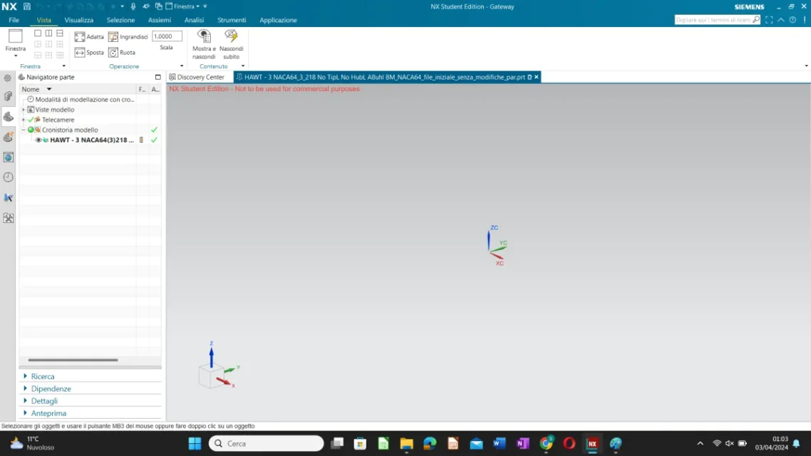
I'm a master student and I'm doing the thesis on wind turbines, but I can't create the solid of the shovel. I imported geometry from an external file that I can't edit.

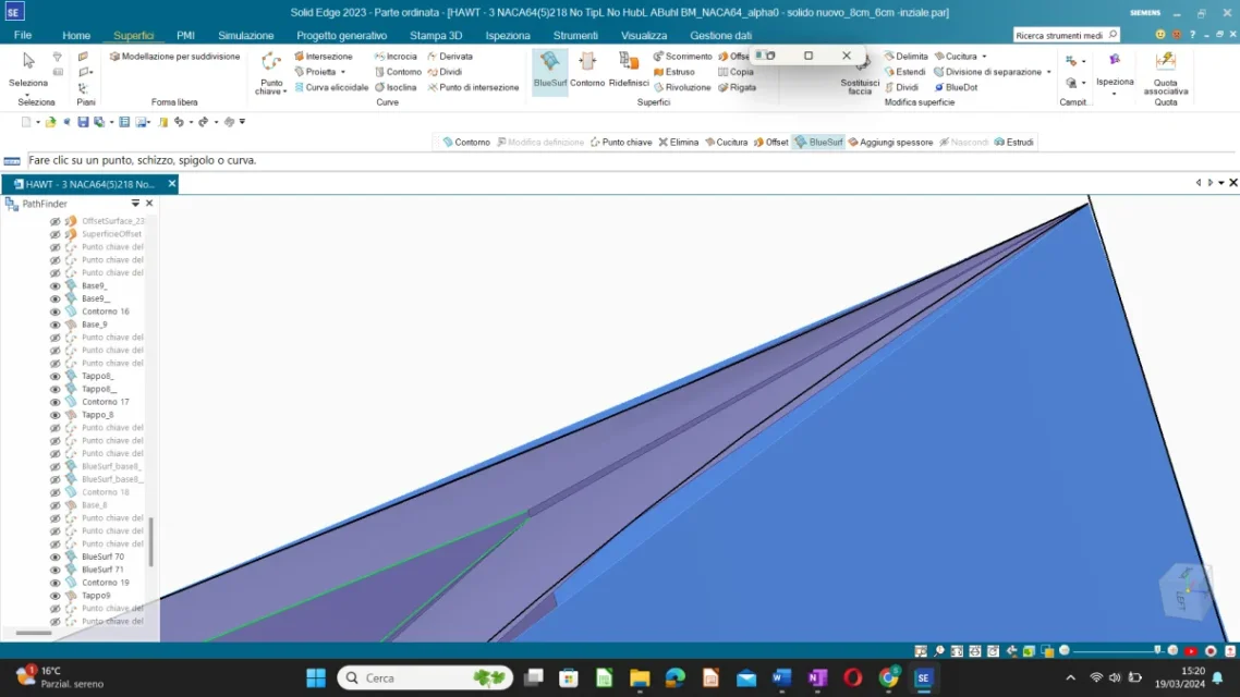
the shovel is divided into cross sections connected to each other by two curves (leading and trailing edge). I created the lateral surfaces between two adjacent cross sections. I have to create the solid of the shovel with variable thickness, i.e. I have to divide the shovel into 4 or 5 parts with their inside constant thickness. I tried both the 'experiment' and the 'offset' function by creating an internal surface and two closing surfaces as caps above and below.
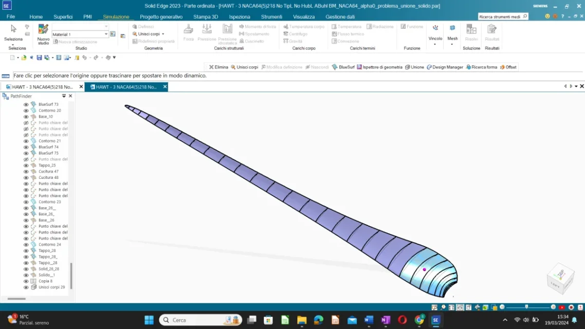
  1. If I thicken two adjacent surfaces I have this error "zero-thickness (non manifold) body: the resulting intersection is not supported", so I alternated solids created with offsets with others created with thickening.
  2. the airfoil of the generated offset surface has open lines and not closed therefore I created other lines and surfaces to prevent there being holes. tolerance is set to 1 mm to avoid problems. the surfaces thus created do not seem to intersect, in fact they cook correctly, the problem is to combine the different solids (the one created with thickening and those with offset) in one. I have the same problem even if I merge only solids created with offset.
By inspecting geometry through the appropriate tool, it tells me the 'face face inconsistency' error in some areas.

If you can solve the problem of zero-thickness body, the thickening function would be the simplest and most effective.

I've been working on it for a long time and I'd really appreciate it if anyone could help me.
Thank you very much in advance.

in case you do not open zip files:
 

Attachments

simone9999 a tip: share saved files also in step, as they are can only be opened by who has your own version of whether (students, educational or what's his name? ).
 
Good afternoon, sorry, I didn't see the answers and I was trying to move on alone but I couldn't do it much.

I opened the parasolid file but I can't view the solid... I put the screenshot in the attachment.
Thanks again.
 

Attachments

  • Screenshot (74).webp
    Screenshot (74).webp
    46.2 KB · Views: 12
simone9999 a tip: share saved files also in step, as they are can only be opened by who has your own version of whether (students, educational or what's his name? ).
The version is the one for students... I'm sorry you mean 'share the files saved in step'?
if I share files in previous stages of work however you cannot open them right?

I attach the initial file without modifications with only the geometry and the one with only the external and offset surfaces, hoping that it can open. Thank you.

drive if you do not open the attached files: https://drive.google.com/file/d/12rzbhgnwdj9fxeq5j_22-vwfkxea5whm/view?usp=drive_link
 

Attachments

Good afternoon, sorry, I didn't see the answers and I was trying to move on alone but I couldn't do it much.

I opened the parasolid file but I can't view the solid... I put the screenshot in the attachment.
Thanks again.
the parasolid is of the terminal part of the shovel that is very long, it could simply be a visualization problem and then try to make a fit of the graphics area. It might be a student problem, but I can't help you here.
 
the parasolid is of the terminal part of the shovel that is very long, it could simply be a visualization problem and then try to make a fit of the graphics area. It might be a student problem, but I can't help you here.
ok now I see the parasolid well, but in the path finder I only see the finished solid and not all its parts (superfici, curves and cross sections etc.) so I can not select the individual entities to understand how you created the solid.
However thank you so much the result I should get is this: a solid with variable thickness. . How exactly did you do that?

Thanks again
hi, to make the solid, I used nx and some tuning of the internal surfaces. That's why I wrote that it takes time. There are two types of problems in surfaces Internal: one where there is a change of offset creates a gap that you need in some way to manage (with nx is quite simple), the other is that the offset of contiguous surfaces can lead to overlaps, due to the different curvature, which also require adjustments.
1712038277579.png
 
Okay, thank you very much. Excuse me how can I import a solidedge file (.par) in nx student version?
It gives me these errors in the picture. (also solid edge is student version).
 

Attachments

  • Screenshot (86).webp
    Screenshot (86).webp
    48.1 KB · Views: 4
  • Screenshot (88).webp
    Screenshot (88).webp
    33.1 KB · Views: 3

Forum statistics

Threads
44,997
Messages
339,767
Members
4
Latest member
ibt

Members online

No members online now.
Back
Top