lucignolo_one
Guest
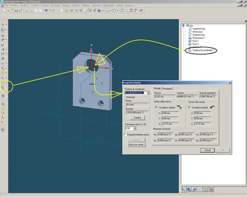
I would have some questions to ask you that they did not find answer on the program guide and in the exercises.....premetto that I have the version 14 of solid edge1)The distances of the mass center towards the x-y-z plans are calculated starting from the origin of the latter and therefore if there is no symmetry in the component or is disapproved it will be necessary to create a new coordinate system and calculate the center on that to have consistent results...right?
2)Is it possible to insert the baricentro automatically in the table? or is it only possible to do so by drawing a point with the coordinates of the baricentro of the piece(or the assieme) of interest?
3)It is possible to change a quota by inserting in its place a word, a letter, a symbol etc. (I tried with the prefixes and suffixes but the value of the quota always remains).
4)in the express route environment, is it possible to create a path of a pipe by interspersing it with components (valves) that have no other "point of support" if not the tube itself?
Thank you.