lelepanz
Guest
Okay.I start with your last statement.
in the civil field the tas are no longer used unless, I think, in limited cases, see here:http://www.edilnotizie.it/2009/05/n...-14-gennaio-2008-in-vigore-dal-1-luglio-2009/will your loft be deposited? You should contact the technical office of the municipality where the artifact will be installed.
Either way, I don't know them, and I couldn't help you.
coming to the study in question I imagine that a and b you have already sized them (you have made a due assessment of the loads agents and distributed for the zones of influence).
If you have done the above you are able to study the beam c.
I'm telling you that now you have only one part of the actions that push the mountaineers (and the fixings to the ground), to have all the actions you have to study also the beam d.
You will conclude that the mounts are subject to deviated displacement.
Hi.
Thank you.
We start from the first point:
I don't have to deposit anything, so it's good for me to dimensionalize with the ta method.
a and b I sized them starting from the assumption (perhaps wrong) that they are 2 beams stuck at the ends subjected to 4 loads concentrated in proximity to the supports of the feet (as from drawing attached).
then carry the binding reactions of the beams to and b on c.
and the beam will be subject to bending-torsion (imagining it stuck).
Right?
![TRAVE_A-CARICHI - [INCASTRO].webp](/community/data/attachments/14/14728-7f94a3ba7ac586d02031669998e9135f.jpg?hash=CUQ0RskzHq)
![TRAVE_A-DEFORMATA - [INCASTRO].webp](/community/data/attachments/14/14729-6e2308a0b26d37a06183d48382a2917f.jpg?hash=-d98TmlxNP)
![TRAVE_A-NODO-K - [APPOGGIO].webp](/community/data/attachments/14/14730-7c5ea5ca8780a5998c7f848f784ecfa6.jpg?hash=jseVPkuKVV)
![TRAVE_A-NODO-H - [INCASTRO].webp](/community/data/attachments/14/14732-d0648ba3029f0d04f83a779d8ffb24ff.jpg?hash=kA88BGuggv)
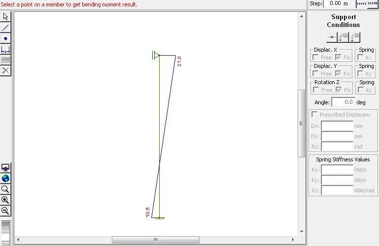
![TRAVE_A-DEFORMATA - [APPOGGIO].webp](/community/data/attachments/14/14733-3d55e06855c6d65e5c724e27b0a4bfef.jpg?hash=yQ_0pAqMI0)
![TRAVE_A-NODO-K - [APPOGGIO].webp](/community/data/attachments/14/14731-7c5ea5ca8780a5998c7f848f784ecfa6.jpg?hash=jseVPkuKVV)
![TRAVE_A-MOMENTI - [APPOGGIO].webp](/community/data/attachments/14/14734-74f70cf8c724306efd6c2df4e11b66a7.jpg?hash=7uRAhEGOS6)
![TRAVE_C-DEFORMATA - [APPOGGIO].webp](/community/data/attachments/14/14736-37a228e43aba398472377d81e5d3efc7.jpg?hash=ErX8jWDWJQ)
![TRAVE_C-DEFORMATA - [INCASTRO].webp](/community/data/attachments/14/14737-11742ecb3e6e5b74b51473271d18cb82.jpg?hash=nuZsef5fqH)
![TRAVE_C-NODO1 - [INCASTRO].webp](/community/data/attachments/14/14738-5642022d42e7674c43cd441bdcc98299.jpg?hash=DC-XXXNDnn)
![TRAVE_C-NODO2 - [INCASTRO].webp](/community/data/attachments/14/14739-4c610303d26d03bdef2691ff422a3cdb.jpg?hash=9UfT8QZsUF)
 attentive to the intersection between a and b, among other things there is also bolting. try to make a bug as from the following procedure.
")