• This forum is the machine-generated translation of www.cad3d.it/forum1 - the Italian design community. Several terms are not translated correctly.

special extraction from total

  • Thread starter Thread starter andream12
  • Start date Start date

andream12

Guest
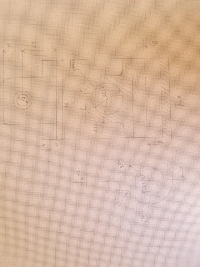
hi guys, I would kindly need an opinion on the extraction of the detail n°1 from the drawing together. I allowed myself to do it on paper millimeters as I am very insecure, especially to have correctly imagined how the piece is done and therefore to have done well the views. thank you in advance to those who will help me.
 

Attachments

  • 16871674565924749257441242844729.webp
    16871674565924749257441242844729.webp
    46.7 KB · Views: 81
  • 16871674824441362473968837732825.webp
    16871674824441362473968837732825.webp
    164.5 KB · Views: 73
but blessed God rotate these images... and look at them on the monitor before you publish them that you have a hard time reading them. you had already been told!! !
here is the image a little more readable
 

Attachments

  • 16871674824441362473968837732825.webp
    16871674824441362473968837732825.webp
    281.8 KB · Views: 67
Last edited:
Bye.
then, in your sheet of paper millimetre, I leave the layout of the views, quotas, etc.
the part that contains the ø30, with outer r22, must be 120mm long, 60mm per part of the axis, with 2 holes for grani m8
then the side view, the one where you see the ø9 (ø9=m8?), delete it as you do not need.
Hi.
 
- you have indicated a b-b section that you do not understand what it is for and what you indicate
- the a-a section must be put, unless special needs, on the side of the projection
-pex, deficit, non-compliance with any known norm
-what relationship is between the top view and the other two is a mystery; but did the projections teach you? ? ? ?
- hidden lines these unknown

I do not waste time comparing it with the exercise because that is the last of the problems.
to summarize: read hundreds of discussions about quotations because you are far from a correct design exactly as in your other discussion that you have abandoned
 
Thank you for your comments. hidden lines are not required for examination. I would kindly like to have clearer where the view from above is wrong. As far as the quotas are concerned, some will certainly miss them, but they do not comply. .
 
but that they do not comply.. .
the text must always be paralleled and above the quota line and should be oriented upward or right, the texts of your vertical quotas instead. . .
I would study the regulations
then lacking the axes of halfria
the text on the section arrow should be put horizontal
I would kindly like to have clearer where the view from above is wrong.
use a compass and make projections, but I'll give you a little help: on the left the body is 54 wide, is it wide?? ?
hidden lines are not required for examination.
hidden lines must always be put, except in cases where they go to create confusion in the reading of the drawing... And it's not your case. hidden lines serve to take references between the various views and thus make it more understandable what you are looking at. Your high view, which is wrong for me, tells me nothing because I cannot relate it to other views; you made the base 75 as wide as the horizontal hole of the lower part but the base has 18 thickness while the hole is 27... without hidden lines that make the drawing clearer I wonder - how the fuck does it stand?? ? ? -

remake the drawing as if I had to introduce it to the teacher and not as a draft to see if you are on the right path
 
Good evening, come back. I am aware of the fact that I should show you complete, but since I realized that the problem already arises from the projections, I want to show you the views so that I can leave the construction lines specifically to clarify better in case I had wronged. I'm very doubtful about the double hole. for the quality of the image I tried to do as best as possible. thanks again in advance
 

Attachments

  • 16871964480122391582845966107933.webp
    16871964480122391582845966107933.webp
    20.3 KB · Views: 50
attached the most contrasted image.
the projection lines if the vupoi leave must be very thin, otherwise the design is not understandable.
the lower projection, which is in fact what you have to get completely while the other two you have to "only" copy them, is wrong; What are they and where did you see those piles that you sell in the lower view? Where does that double circle come from on the lower base?

you should print the image of the exercise, highlight the contours of the component and then with the ruler draw the lines to see what to the right corresponds to the left.

for the image if you take the photo with the cell phone avoid using the flash and do not shoot us over a direct light; use cell phone image retouching to change brightness and contrast
 

Attachments

  • 16871964480122391582845966107933.webp
    16871964480122391582845966107933.webp
    39.9 KB · Views: 38
As for the double hole, I hypothesized that the tree went there. for the pegs would be the holes where there would be the m8 vines seen from the left view. in any way while projecting, it is difficult to understand what the geometry of the correct view is
 
for the pegs would be the holes where there would be the m8 vines seen from the left view.
How does a hole protrude??? ? ? ? ? ?
As for the double hole, I hypothesized that the tree went there.
How does a tree go into two holes? have you seen that in the section the holes are perpendicular to each other while in your projection they are perpendicular, but on the same axis??? ? ?
 
I hope I have corrected.
 

Attachments

  • 16872026967301678622045002433772.webp
    16872026967301678622045002433772.webp
    30 KB · Views: 38
No, it's almost identical to before.
I repeat:
if in the section you have two elements whose holes are arranged at 90° between them and are staggered (a parallel to your left view and a perpendicular to your right) as they do in the lower view to be on the same floor?
if by hole you mean a cavity, i.e. absence of material, how do you draw two cylinders that are dirty?
isn't that by chance what you designed instead of holes could be a piece of the body that contains the right hole in the section? Isn't that that rectangle you drew in the view below you should replace it instead of the two cylinders?
 
from the view from above theoretically, should I not only see the hole that in the section is the one on the left where the tree goes? the right hole, on the other hand from above, is it not right? what I imagine is that you see only the cylindrical parts that then crushed are the two rectangles
 
Unfortunately, you're not getting the projections.
take two glasses or any other cylinder underhand, place them as in the top view, one vertical and above this one horizontal. consider them as a unique body
90° turn right; ideally match your section... Yes.
back to the starting position and rotate 90° towards you to get the view from above, seems to what you did? No! !
 
the layout is correct, and I would like to see after the suggestion, but the design remains wrong.
compare with other fellow students to see where you're wrong
 
Thank you very much. by wrong design what do you mean? of course everything is missing beyond the views
 
is meant that representation is not correct.
I don't know what to say, you pulled projection lines without understanding what they actually represent.
I only point out this: in the view below where you see the holes m8?
 
actually my problem is just imagination of the piece. for the holes I would think so
 

Attachments

  • 16872457115328445708982997675749.webp
    16872457115328445708982997675749.webp
    27.8 KB · Views: 61

Forum statistics

Threads
44,997
Messages
339,767
Members
4
Latest member
ibt

Members online

No members online now.
Back
Top