• This forum is the machine-generated translation of www.cad3d.it/forum1 - the Italian design community. Several terms are not translated correctly.

sprockets and chains

  • Thread starter Thread starter andreaf93
  • Start date Start date

andreaf93

Guest
Good evening to all,
I've been drawing a rotary mechanism made from pinions, chains and chain curtains lately, unfortunately my experience on these specifications is not so much.
I should pass the chain even in the lower part of the central pinion (the biggest one to understand). I don't know if I'm wrong when I insert the sequence into the belt/chain function or if it just doesn't make me do it because the system wouldn't work
Thank you for your help. MKAF00500.webp
 
and what is the problem?
Don't you get the pinion?
Does the chain put you wrong?
Anything else?
 
the problem is that I can't position the chain even at the bottom of the central pinion. as from the pinion placed on the extreme right side goes directly to the lower tendicatena on the left.
 
If you send us a meeting, we'll see it and maybe we'll figure it out. . . .
for the moment in the belt function try to move the selection order of the girths with the darts you find in the function.
 
If you send us a meeting, we'll see it and maybe we'll figure it out. . . .
for the moment in the belt function try to move the selection order of the girths with the darts you find in the function.
I'm sending the witness tonight.
I have already tried to move the order but it is placed in the correct way.
definitely you can't select the same wheel twice.
cannot be selected as the function does not give you this possibility and then I will have to draw the path of the chain manually or does not make you select the pinion twice because even in reality would not be feasible?
Thank you.
 
I'd better put the chains you want to do because in words I didn't understand anything. for the sw chain strap command you reverse the selection orders or with the arrows you reverse inside/outside. to the gas barrel, draw the sketch together and make a normal part.
 
I'd better put the chains you want to do because in words I didn't understand anything. for the sw chain strap command you reverse the selection orders or with the arrows you reverse inside/outside. to the gas barrel, draw the sketch together and make a normal part.
I'll tie you hand-made pattern of how I'd like to make the chain ring.
I'll send you the step tonight.
 

Attachments

as I have already said you can't select the same wheel twice (the second selection removes it from the list)
what you can do is put a second equal wheel to select and then hideImmagine.webp
 
It is true, the rota must be copied and in the properties "excluding the distinct". alternative create a flexible adaptive sketch and create a part not with the belt tool
 
as I have already said you can't select the same wheel twice (the second selection removes it from the list)
what you can do is put a second equal wheel to select and then hide
thanks to the advice so it works perfectly, but now I have two things that I cannot solve:

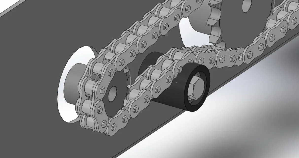
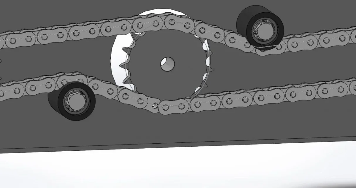
- how to perfectly mate the pinion teeth with the chain: Foto Denti e Catena.webp- how to combine the chain completely (look at the bottom of the chain where it is known that it is not perfectly united: Accoppiamento catena.webpFinally I attach the link http://ge.tt/4owkabp2 so you can download the axieme file. Thank you very much
 
- how to perfectly mate the pinion teeth with the chain:
turning the pinion
- how to combine the chain completely (look at the bottom of the chain where it is known that it is not perfectly united:
to match the chain a length of the belt function must be a multiple of the step, it seems rather obvious
 
in reality is the spindle, in solidworks is the same thing.
If you have done everything perfectly you should be able to combine concentricity between chain pin and pinhole tooth.

but does it have a real need to get lost in these futility?
 
in reality is the spindle, in solidworks is the same thing.
If you have done everything perfectly you should be able to combine concentricity between chain pin and pinhole tooth.

but does it have a real need to get lost in these futility?
actually no is just mere principle.
 
I design chains make a profile like straps with the maximum cross section and good night. . . .
 
meccanicamg said:
I design chains make a profile like straps with the maximum cross section and good night. . . .
certainly also because otherwise there is no wonder if the software slows down. .. Let's face the bearings with all the spheres of the second image of the post #11 and the movements of the model begin to go hiccup.

andreaf93 said:
actually no is just mere principle.
do for mere principle the precise on the pinions and then the chain intersects the roller blinds by distorting the length of the path
 
to match the chain a length of the belt function must be a multiple of the step, it seems rather obvious
I set as belt length at 838.2mm or a multiple of 12.70 (my step). But I still don't match the chain.

(the tendicatena is right I have to fix them, I thought to make a concentric hole to the tendicatena of a larger diameter about the thickness of the chain itself and select that hole as the path of the belt).

allego together updated http://ge.tt/8bzxacp2Thank you.
 
Sometimes I had to match the whole thing, but you have to consider how the chain approximates the circle and basically you have to draw the polygons that have the axes of the chain rollers as vertices and connect those with straight strokes that must be exactly multiple of the step. moving the blinds you should find the phase of the whole system. definitely, after the modeling, it is all well stuck and does not rotate anything. the length of the developed chain changes continuously, as well as the input and output position of the chain from the wheels and if you want to accurately simulate it there are these limits. try to sketch a toothed wheel with a large step and a modest number of teeth and you will see that this singularity will be evident. to realize a real set able to move you should mate all the shirts by hand and have the correct degrees of freedom on the curtainrs.
 
Sometimes I had to match the whole thing, but you have to consider how the chain approximates the circle and basically you have to draw the polygons that have the axes of the chain rollers as vertices and connect those with straight strokes that must be exactly multiple of the step. moving the blinds you should find the phase of the whole system. definitely, after the modeling, it is all well stuck and does not rotate anything. the length of the developed chain changes continuously, as well as the input and output position of the chain from the wheels and if you want to accurately simulate it there are these limits. try to sketch a toothed wheel with a large step and a modest number of teeth and you will see that this singularity will be evident. to realize a real set able to move you should mate all the shirts by hand and have the correct degrees of freedom on the curtainrs.
thanks to the advice, do you think I should draw polygons only on the pinions or even on the curtains? thanks
 

Forum statistics

Threads
44,997
Messages
339,767
Members
4
Latest member
ibt

Members online

No members online now.
Back
Top