• This forum is the machine-generated translation of www.cad3d.it/forum1 - the Italian design community. Several terms are not translated correctly.

static analysis

  • Thread starter Thread starter blubossa
  • Start date Start date

blubossa

Guest
Bye to all,
I press that on the simulation module I know little, so I try to figure out how to solve a problem that I presented myself...
In practice I have an iron structure that has to hold two loads of 4000 kg and 3500 kg.
the structure is divided into two on customer's request for maintenance and cleaning........
attached the structure with the two loads that I simplified with two solids...boys I don't know exactly where to start... .

Thank you.
bb
 

Attachments

If you place an image we can answer even seeing from the phone.

however be:
- define the bond types of the structure (inks, hinges, trolleys, supports etc.)
- define the structure as model 3d, set gravitational weight to also have deformation by own weight, if the forces you need to apply are concentrated you must first draw the areas of application and divide the surface, generate standard mesh, solve the study fem
- if there are problems, it should be considered the beams as solid and not as beams, especially if you want to see the localized behavior between the joints. If the mesh doesn't have to use the one based on curvature and not congruent, in order to bypass all the problems of localized meshatura.

follow some tutorials to learn.
 
Hi.
Here are the pictures, in principle I understand something about what you told me and watching some videos, but here are the pictures and then I hope to understand more with your suggestions.
also because I would like to understand how to interpret the results that are obtained....

bb
 

Attachments

  • SOSTEGNO PER ANALISI-solo-struttura.webp
    SOSTEGNO PER ANALISI-solo-struttura.webp
    45.6 KB · Views: 5
  • SOSTEGNO PER ANALISI.webp
    SOSTEGNO PER ANALISI.webp
    40.4 KB · Views: 2
the structure is a little mingherline but the yellow attacks are the most stressed and should be analyzed thoroughly. the structure could open by bending and drop the parallelepiped by the yellow supports.
 
I try to say mine, even if I don't know about analysis.
first u n couple of questions:
- the yellow supports have holes, but on the frames there is no counterplate. What are the holes for?
- Do you have a chance to raise the structure so you can put a cross that joins the two sides? the structure is tied only below, but if there are lateral movements especially of the upper load opens as an apple.

My comments are:
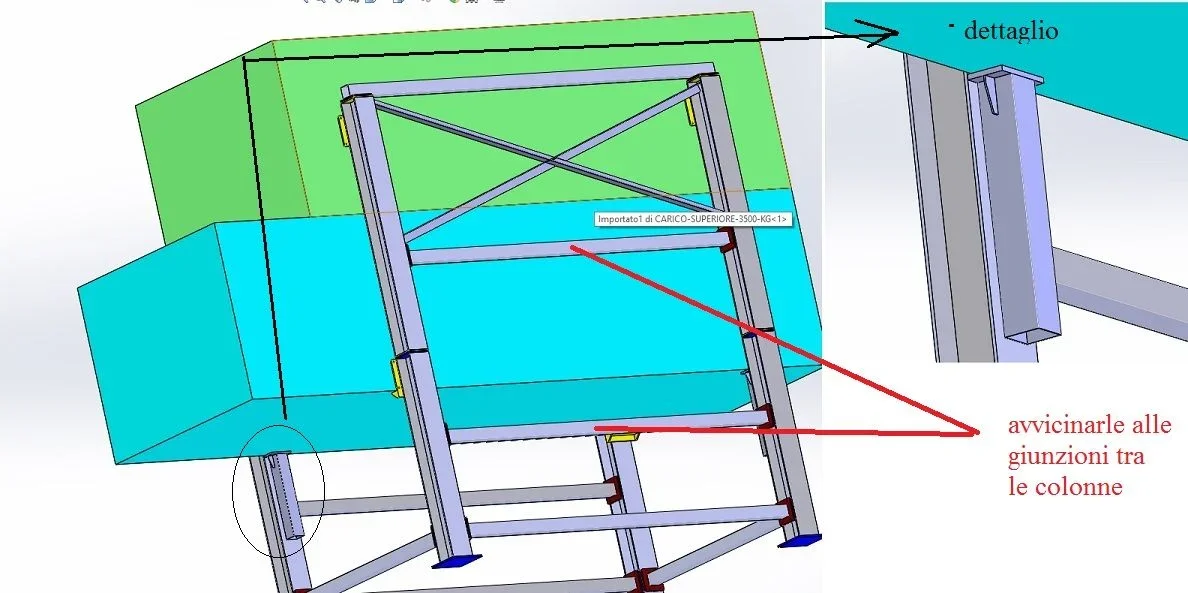
-put cross reinforcements laterally to stiffen the structure in all directions (see picture)
-put reinforcement tissues on all plates
-instead of putting yellow plates to understand whether dismantled or not) weld a vertical tube and close it with a beautiful plate (see detail)
-In addition those side crosses I would approach you as much as possible to the junction between the columns (see picture note)
Immagine.webp
 
I try to say mine, even if I don't know about analysis.
first u n couple of questions:
- the yellow supports have holes, but on the frames there is no counterplate. What are the holes for?
- Do you have a chance to raise the structure so you can put a cross that joins the two sides? the structure is tied only below, but if there are lateral movements especially of the upper load opens as an apple.

My comments are:
-put cross reinforcements laterally to stiffen the structure in all directions (see picture)
-put reinforcement tissues on all plates
-instead of putting yellow plates to understand whether dismantled or not) weld a vertical tube and close it with a beautiful plate (see detail)
-In addition those side crosses I would approach you as much as possible to the junction between the columns (see picture note)
View attachment 48045
Hi.
Your comments are very clear, and I agree fully.
yellow plates have holes because on the load there are other plates welded with threaded holes for bolts m12

I saw that you opened the step to suggest solutions, I hoped, with this opportunity, to learn how to make a static simulation to start learning how to use this sw....

Thank you.
bb
 
therefore the details blue and green are fixed by bolting to the structure, correct? in this case the stiffening is done by the load itself; even if a couple of extra reinforcements do not hurt (except weight constraints).

the simulations I can't do and the dedicated module I never opened it
 
therefore the details blue and green are fixed by bolting to the structure, correct? in this case the stiffening is done by the load itself; even if a couple of extra reinforcements do not hurt (except weight constraints).

the simulations I can't do and the dedicated module I never opened it
yes the loads are bolted, I actually thought to add some extra reinforcement...

...we hope it keeps everything......

bb
 
as other users said the weak point should be the tooth on which it supports.
Don't you have a way to increase it?
 

Forum statistics

Threads
44,997
Messages
339,767
Members
4
Latest member
ibt

Members online

No members online now.
Back
Top