• This forum is the machine-generated translation of www.cad3d.it/forum1 - the Italian design community. Several terms are not translated correctly.

surface conversion in sheet metal with catia

  • Thread starter Thread starter gemini179
  • Start date Start date

gemini179

Guest
Good evening,
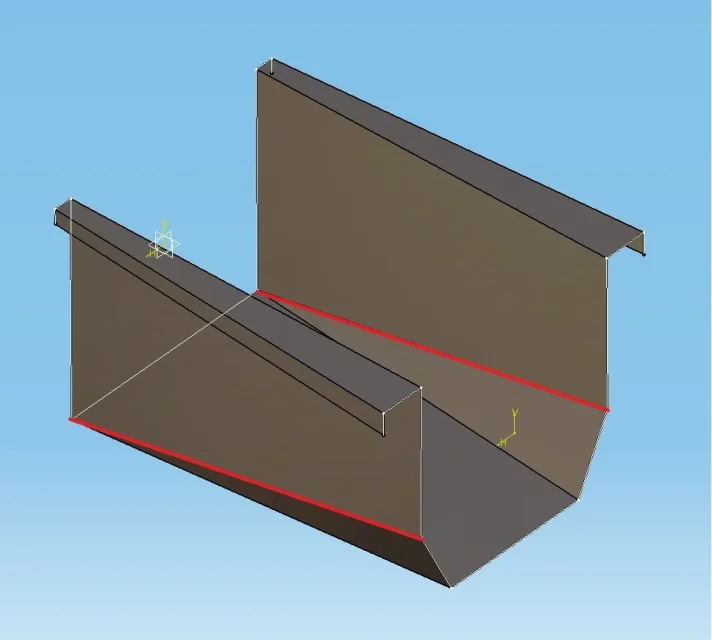
I ask the community if there is the possibility of converting a surface profile (obtained as loft between two sketches) into sheet metal.
Attached you will find the photo of the part in question.
thanks to the attention
 

Attachments

  • FL_a.webp
    FL_a.webp
    34.4 KB · Views: 3
  • FL_b.webp
    FL_b.webp
    8 KB · Views: 1
thanks for the suggestion, although I haven't solved yet. I attached the file hoping it could be more help to understanding.
 

Attachments

Do you need the profile exactly like this without a minimum bend radius? This is because, in my opinion, you should reach the living edges and then, through the command "hopper" you convert your surface profile into sheet metal.. .
 
Do you need the profile exactly like this without a minimum bend radius? This is because, in my opinion, you should reach the living edges and then, through the command "hopper" you convert your surface profile into sheet metal.. .
Good morning.
I tried to create a fitting for each edge (rough=3.4, for quarry from 20,lamiera thickness 1.5mm) ,but when I create the coupling point by point, in the multisection hopper function, something is not going and caia fails to return me the sheet profile.
I attach an image highlighting in red the folds that present problems.thanks still
 

Attachments

  • FL_Problem.webp
    FL_Problem.webp
    27.6 KB · Views: 3
thanks to all those who have read this discussion and have taken their time to solve it. I just solved by reversing the orientation of the material and using the fl_b.zip file in which I modified the sketches by radiating each edge and adding a fold on a profile so as to get the same number of couplings between the two profiles.
Thanks again
 
this is proof that I did very quickly, adding rays.
so as it is I do not think it can make of fold as the piece presents a twist.
Anyway, if you solved it's okay.
View attachment 43276
thanks xxfast, I attach the exact development file. in the table I can't pull out the fold axles, although popping them up in the options of the view. Maybe you can (hopefully)
 

Attachments

Usually with the sheets drawn from the surfaces I always have problems displaying the bending lines.
try to insert the folds with the fold command.
If I have time to try...... .
 
Thanks again, but I find it strange that the hopper function does not give the fold lines in drawing. Perhaps there is some passage that we ignore
 
may also depend on the software version. .
However I did a test using another approach, i.e. starting from the solid, which typically works best regarding the fold lines.
I'll give you an example done quickly as an example.
Bye.
View attachment FL_B_ok (2).zip
 
thank you xxfast, I followed step by step your work and finally in the table putting the fold lines (assi) appear. Of course it is a pity that from the hopper function in sheetmetal design it is not possible to get the same result. also because getting a sheet development, without being able to locate the fold lines,it is quite useless. Thanks again
 
Please.
Unfortunately I don't know if it's a software version problem or anything.
I never did....

:finger:
 

Forum statistics

Threads
44,997
Messages
339,767
Members
4
Latest member
ibt

Members online

No members online now.
Back
Top