• This forum is the machine-generated translation of www.cad3d.it/forum1 - the Italian design community. Several terms are not translated correctly.

technical drawing exercises

thanks to all of the answers, as soon as I reopen the pc I try to respond better, my exercises are in extracting the component and making a sketch quoted, but for now I am trying to get used to the eye to immediately recognize the component so as to understand at least what I am drawing
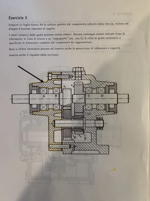
recognize by giving it an identification name helps for commercial components while for construction ones it has a marginal value because, for example, call component 1 of the last attachment: external body (which by the way does not make anything imaginably), shirt, cylinder, compass... does not allow to extract more easily graphically.
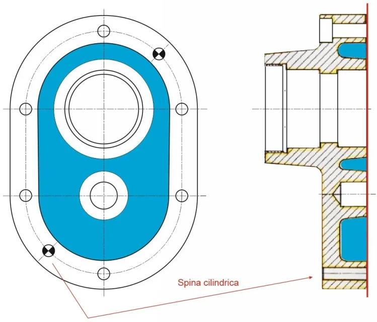
an exercise you can do is to highlight with different colors the contours of the various components, this helps you understand how to recognize, what is logic, in a assembled different components without having to design them individually in advance.
 
in fact in this exercise I tried to draw the component 1 beginning with highlighting the contours, I will follow the advice thanks a thousand
 
good evening to all and good Sunday, I am doing this exercise of representation components and I find myself in difficulty in two things:
1) I do not understand how the quarries I think are made of lightening the structure? Are they ovals like I did or are they all independent digging?
2) how can I better organize quotas? I have noticed being a lot and I find myself having created confusion in my opinion, having little space available

thank you in advance and good evening
 

Attachments

  • image.webp
    image.webp
    73.1 KB · Views: 57
  • image.webp
    image.webp
    123 KB · Views: 63
1) I do not understand how the quarries I think are made of lightening the structure? Are they ovals like I did or are they all independent digging?
ask yourself this question: what should we be housed in? un cuscinetto.
How is a bearing made? It's cylindrical.
can a cylindrical element be mounted in a square quarry?
your design so it is wrong
2) how can I better organize quotas? I have noticed being a lot and I find myself having created confusion in my opinion, having little space available
more than anything else you're misquoting also because geometry is wrong (however to correctly definate geometry needs another view besides the sectional one you see in the examination track).
the design is placed in a sheet suitable for representation and properly oriented; if instead of vertical the sheet you put it horizontal you will see that you can use all that space below
 
no I mean these caves, those of the bearings is the central circle, for the laying the professor obliges us to use vertical deposit for sheet a4
 

Attachments

  • 5053947B-D94C-4938-B3EF-7F824B56986D.webp
    5053947B-D94C-4938-B3EF-7F824B56986D.webp
    83.1 KB · Views: 61
in 2021 there is still the "cutting of the sheet". ... ultra archaic term.

the small quarry... Actually it is a flat wall with a conical cylindrical protuberance where to insert the bearings.

The big quarry below follows the middle crate. In fact it is a thin wall with a hollow cone only where there is the seat of the pin.
 
or I mean these caves, those of the bearings is the central circle,
without another view it is not possible to know. so if it does not exist it is okay any form.
are lightenings made melt.
scattered observations:
the upper hole is wrong:it makes no sense to make a hole with the final threaded part if the thread is present in the other half of the carcass of the reducer.
the hole before the bearings, where the flange is mounted, is threaded. It is understood by the double line and by the fact that otherwise the flange would not be blocked in any way.
the worked holes do not quote from the external geometry which is a rough element, but from a known reference that in this case will be the central hole of the bearings.
in the section lack the lines of revolution
proportions are not your strong
 
thanks to the shortcomings, for the proportions sincerely to the prof does not affect the accuracy and since I am doing free hand tests for now neither to me, obviously the intention w that to arrive to faithfully replicate the piece but always for reasons of encumbrance in the sheet in this case it was not possible
 
1) I do not understand how the quarries I think are made of lightening the structure? Are they ovals like I did or are they all independent digging?
2) how can I better organize quotas? I have noticed being a lot and I find myself having created confusion in my opinion, having little space available
hi christian, surely if you had kept proportions and used a ruler would have been easier to understand.
the exercise does not refer to the view from the right and for the quotations you do not need, also because you would need information that you certainly did not give as unnecessary for this exercise (e.g. number and position of fixing screws, thorns, etc.).
in the right view of the lid that I attach, I predicted 6 screws that necessarily have to be as much as possible equidistant to have a uniform tightening on the whole plane and two thorns that however I predicted staggered than the one indicated in the original design dissected because they should be preferably opposed symmetrically and in the original position (which should have been in false sight because there should be a fastening screw) they had to do the discharge of the air 100 years ago.so you just need to draw and quote the section in which you have all the elements you need, even the excavations, in fact it is only one excavation (blue area) placed on a single level from which emerge the two hubs and of which you will have to quota only the depth and the sforms beyond, of course, the rough diameters.
this exercise has been assigned to you to evaluate your ability to understand and insert quotations, dimensional and geometric tolerances and wrinkle degrees determined by machining (being a piece obtained from cast iron casting and worked on work centers you only have two degrees of roughness).

only the quotated section is required, the vertical a4 sheet is sufficient.
 

Attachments

  • Esercitazione disegno.webp
    Esercitazione disegno.webp
    62.3 KB · Views: 49
2) how can I better organize quotas? I have noticed being a lot and I find myself having created confusion in my opinion, having little space available
I attach two images from which you can draw inspiration for quotations.
one is a lid with some analogy with your in which you can see the quotation of the casting excavation and the hubs, the other is a bearing holder.
I hope they can help you.
 

Attachments

  • Esempio mo.webp
    Esempio mo.webp
    32.8 KB · Views: 44
  • Esempio cop.webp
    Esempio cop.webp
    48.1 KB · Views: 48
Thank you so much! In fact I realized I could not know how it was without another view but the professor wants us to imagine how it can be and that we use the necessary views in a complete way, however thanks both for the explanation and for the quotation, in case I had the right view the quotation that I did is right?
 
So you have to do the view from the left too? If so, try to recreate it, you have all the elements to do it.
the view from the right that you have done is not real and the quotas are arranged in a disorderly and not rational way. look at the images I have attached and try to put the full quotas on the view I gave you and on the relative section, then attach the elaborate that we correct it.
If you can make a technical design and not a sketch thrown there, you don't have to think about making the least necessary to please the teacher (if it's okay with him), you have to think that one day you will have to do it for a company and there you won't have discounts. :
 
OK thanks soon I try to do it again, more than do the least to please the teacher does not want us to use tools like ruler and compass and I have to get used to the hand otherwise I arrive to the exam and I can not do a straight line without ruler, thanks anyway of the advice and rightly having done the wrong geometry I can not quote correctly
 
one is a cover with some analogy with your in which you can see the quotation of the casting excavation and the hubs

Good evening, can I ask you what these living corners are? Is that one quarry made for fusion?
Thank you very much
 

Attachments

  • InkedEsempio cop_LI.webp
    InkedEsempio cop_LI.webp
    53.7 KB · Views: 39
What are these living edges?
they represent a widening of the cover wall to be able to practice the fixing holes: you can see well in the left view of the complete drawing that I attach (discuss the quality of the collage but I have a small scanner and the original paper is an a2).
I also reported the paperwork that can serve you as a track to understand the basic information to report in the drawing.
Is that one quarry made for fusion?
Yes, it is a single quarry from which emerges the ribbed hub bearing (as in your case) plus that swelling that you see in the upper part that is nothing but a popspec (you see it well in the left view at the top) in which the hole for an oil cap will be practiced (on request).
 

Attachments

  • Esempio cop.webp
    Esempio cop.webp
    41 KB · Views: 36
But where does it say you have to do side view?
according to me you have to quote only the section
 
But where does it say you have to do side view?
according to me you have to quote only the section
I think so too, but at the last examination the rejection of some people was determined by: you had to imagine the view even if it wasn't because it was necessary
 
Good evening to all and good Friday, I wanted to share with you this exercise to ask you two questions:
1)Is the plug hypothesized and correctly represented?
2)the primitive of a conical wheel in the plant after which circumference should be represented? after the outer head circumference or after the inner one? in many cases it is always after the most external but seeing it in this exercise I would have put it after the second.
I take the opportunity to ask for a general opinion of the drawing, in the end the professor will allow the use of ruler and compass.

the component is number 3
thanks and good evening/part.
 

Attachments

  • WhatsApp Image 2021-07-02 at 19.22.41.webp
    WhatsApp Image 2021-07-02 at 19.22.41.webp
    64 KB · Views: 30
  • WhatsApp Image 2021-07-02 at 19.30.09.webp
    WhatsApp Image 2021-07-02 at 19.30.09.webp
    101.7 KB · Views: 41

Forum statistics

Threads
44,997
Messages
339,767
Members
4
Latest member
ibt

Members online

No members online now.
Back
Top