MassiVonWeizen
Guest
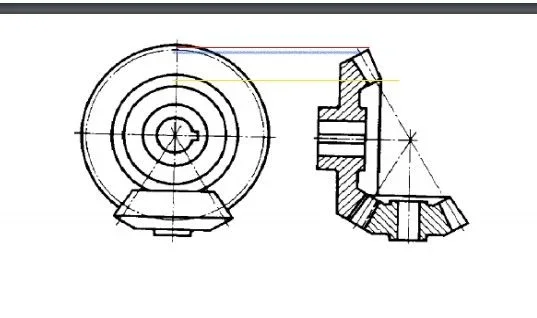
That's not a plug, but the hole in the plug. by turning the 90° section, you would have avoided the break in the upper view.1)Is the plug hypothesized and correctly represented?
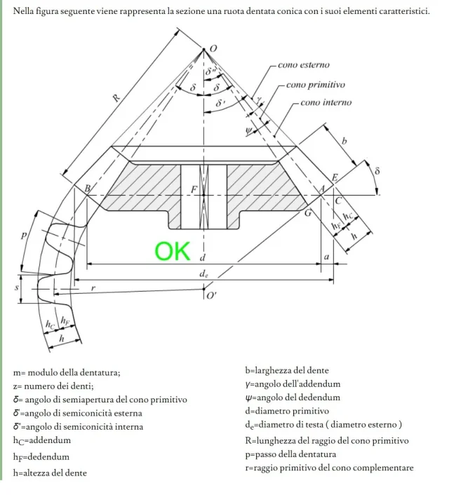
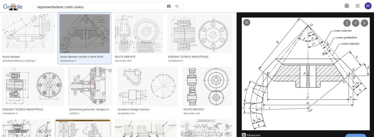
just open a manual and see what is listed with øp2)the primitive of a conical wheel in the plant after which circumference should be represented?
industrial-ideas.com - industrial ideas Resources and Information.
industrial-ideas.com is your first and best source for all of the information you’re looking for. From general topics to more of what you would expect to find here, industrial-ideas.com has it all. We hope you find what you are searching for!
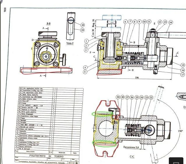
I have a hard time reading the drawing with almost invisible quotas. But the diameter of the hole I can tell you that it is better to put it in the section along with others so the operator does not have to go looking for it around.I take the opportunity to ask for a general opinion of the drawing
(ii) a 3.2.
you have made only one tooth table, but you have two; one with straight teeth and one conical


")
