• This forum is the machine-generated translation of www.cad3d.it/forum1 - the Italian design community. Several terms are not translated correctly.

Termus - ground floor modeling to different odds

simonea

Guest
Hello, they are struggling with the modeling of a cottage that develops with basement floor without heating system, and ground floor;
living area and sleeping area are pt, on two heights (one at zero altitude, the other at +60 cm), connected by 4 steps.
the cover consists of two roofs with two sides (at different quotas), the first covers the living area and part of the sleeping area, the second the remaining part of the sleeping area.

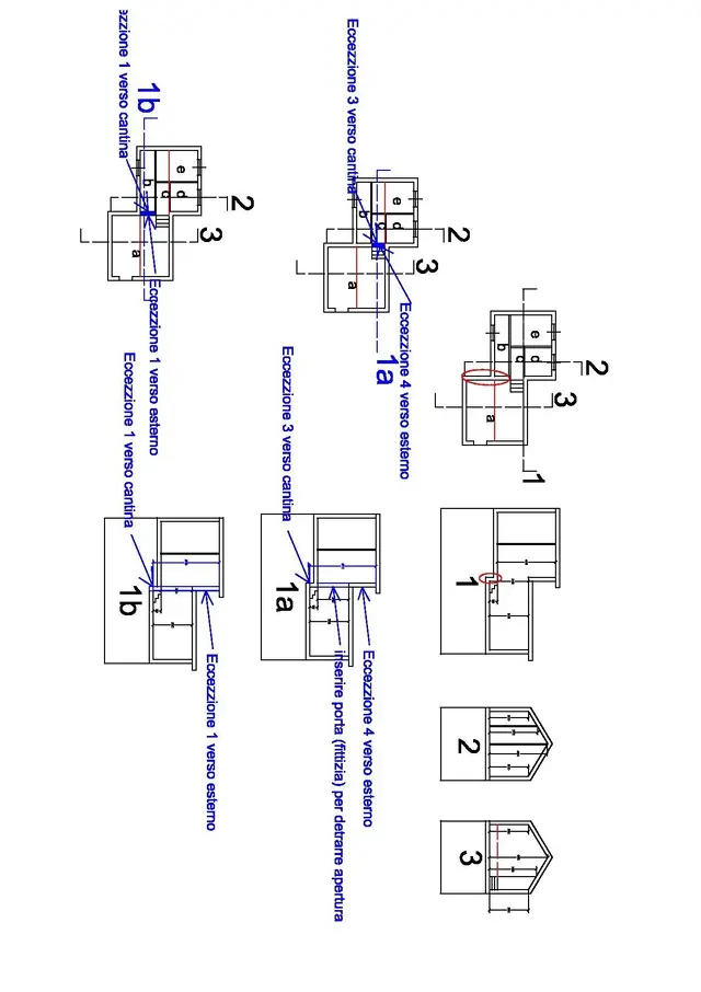
I thought I'd solve it like this:

1 - I create a first level for the living area, of a height of 60, whose upper and fictitious loft;
2 - I create a second level of height is equal to that of the first two-phalt roof (average height) less 60 cm, the living area will have as lower sunbed the fictitious one, the part of the sleeping area that to how cover the roof with taller falde will have as upper sole a fictitious one;
3 - I create a third level of height equal to that of the second two-phalt roof (average height) less height of the first two-phalt roof (average height), the part of the sleeping area that to how cover the taller falde roof will have as lower sole a fictitious loft.

the thermal zone will of course be one, while the dispersed surface will be slightly higher than the real one (see the approximates given by the average of the heights of the two covers).

I realize it's a malicious procedure, I tried to turn to the acca's assistance and told me it was okay.
Trying cn the software I realize a problem, (perhaps nn the only) about the representation of the windows doors and doors that would result divided in two.

according to you how procedure can go??? do you have other ideas or methods to solve similar cases? ? ?
greetings simone
 
In my opinion, it is not correct.
You must draw a "only floor", for the following reasons:
- the floors must be the actual ones, as the dispersions towards the ground/cantina/subtet are the "real" ones
- for scattered walls, i.e. the "part of the walls" that borders with attic/exterior/ cellar you can insert it by "wall exception"
- the heights of the walls (and the premises) insert them into the specific field, individually for each element
- the remaining parts of the walls, bordering between heated environments, are not dispersed and will not be counted
if even the local medesino floors, confine on different environments, you must use "only exceptions".
in the manual is present as comparing the type of your case (it is also represented in a section view - Chapter 9.11)
 
I've seen, but I've got the roof falde problem.
I should do the average of heights and in any case I would have a non-real dispersed surface for the different exposures.
 
...
I should do the average of heights and in any case I would have a non-real dispersed surface for the different exposures.
... I didn't understand, can you clarify better?
to excels you can assign typology, exposure, objects, etc...
basically the "technical data" are all available for calculation (they are not graphically represented) ...
 
[
... I didn't understand, can you clarify better?
Gross dispersing surface (I have not considered thicknesses of soles):
e.g. square plant 5x5, two-phase roof with h to dx and sx 3 mt, h=4,5 mt; east and west exposure 3 mt 3x5=15 sq m,
north and south exposure (3x5)+(1.5x5)=22.5 sq.m.
if I make h average = 3,5 mt would, east, west, north and south 3,5x5=17,5 sq m, which is not the real dispersed surface.
similar situation if calculating the volume.
... you can assign the type, exposure, objects, etc...
basically the "technical data" are all available for calculation (they are not graphically represented) ...
so x represent cn termus my e.g. do:
1)I place the table height at max (in my e.g. at 4.5 mt);
2)for the east and west walls imposed manually h = 3 mt;
3)for the masonry to the north and south I put the exception wall cn the square meters of the triangle (1,5x5).
And the cover loft? ? ?

I couldn't insert quote! ! !
 
Last edited by a moderator:
...
Gross dispersing surface (I have not considered thicknesses of soles):
e.g. square plant 5x5, two-phase roof with h to dx and sx 3 mt, h=4,5 mt; east and west exposure 3 mt 3x5=15 sq m,
north and south exposure (3x5)+(1.5x5)=22.5 sq.m.
if I make h average = 3,5 mt would, east, west, north and south 3,5x5=17,5 sq m, which is not the real dispersed surface.

similar situation if calculating the volume.

so x represent cn termus my e.g. do:
1)I place the table height at max (in my e.g. at 4.5 mt);
2)for the east and west walls imposed manually h = 3 mt;
3)for the masonry to the north and south I put the exception wall cn the square meters of the triangle (1,5x5).
And the cover loft? ? ?

I couldn't insert quote! ! !
for the heights (internal) assigns the relative quota (media ... also weight) each compartment (of the building).
the table height, serves to assign it (with a single input) to all rooms, but it is possible to change it for each single compartment.
in the calculation of measurements/surfaces/ gross volumes the sw sums the heights (cuffs) to the thickness of the walls and/or floors
in each room (clicking on the name of the room) you can access the specific menu of floor and ceiling/tect.

the same for the walls (wall portion).
insert the total height of the wall (black), and on the external face (the triangle) that borders the outside, put the exception wall, in deduction (from the surface - external) with its references.
paratica in the calculation of dispersions, will be considered only the surface of the exception to the outside (the triangle) keep the remaining surface of the opinion, if confined to heated premises, will not be considered
in the case of the roof bordering with the outside, it is possible to assign a tilt coefficient (as in the solitary extinguishments)
the reference to the exposures is calculated by the sw based on the orientation symbol inserted, but for the roof no orientation is calculated (even with the fictitious planes as you had assumed can be identified)


p.s. to insert quotes click on the "quota" button below the message (to quote/quote)
 
... so x represent cn termus my e.g. do:
1)I place the table height at max (in my e.g. at 4.5 mt);
...
no, at each local correct the quota (net height internal average)
...
2)for the east and west walls imposed manually h = 3 mt;
3)for the masonry to the north and south I put the exception wall cn the square meters of the triangle (1,5x5).

...
no, at each wall (extra/segment) of a wall assign the height (internal average, if of the case calculated weight)
for the wall (wall portraits) bordering between two staggered premises, assigns the total height from the floor of the lower room to the ceiling of the high room.
then on such wall, set the wall excretions (in deduction):
- one towards the "external face" to which it checks the dimensions (surfaces) and the surrounding environment, etc... ;
- the second towards the "internal face" with the surface bordering the room
cellar;
the surface that remains on the two faces of the wall will not be dispersed as it borders with heated premises
...
And the cover loft? ? ?
...
select the name of each compartment, and in the extended data of the entity, in the upper loft assigns the inclination coefficient (medium, if there are more hawks) and ponies as boundary "outside"
 
Thank you gfrank, it seems quite clear! !
I try to shape it by following your suggestions, anyway to make a comparison I do the calculations manually.

the thing that leaves me very puzzled was the answer of the assistance of acca!!!

Hello simone
 
I have 5 rooms, the compartment is at a different level than the other 4, (they are connected by the 3 steps.

1)I light my plant;
2) check the heights starting from the sez 2 (or the rooms b,c,d,e),
- perimeter 3mt
-first half-half 3,73mt
-according to 4,44mt
- perimeter 3mt
nb to orthogonal masonry (except for those 2 that are circled in red) to sez 2 as well as to the soles I will give average heights (average between 3 and 3,73 etc.)
3)consider sez 3 (vano a)
- perimeter 3mt
- perimeter 3mt
nb - to the loft and to the orthogonal wall that has the door, I will give average quota between 3 - 4,5 - 3;
while to that circled red I will give:
- at the first stretch a height equal to the average between 3 and 4,5, putting 2 wall exceptions, one towards the compartment equal to the sup of the wall in contact with basement, the other towards vain b indetration always equal to the sup of the wall in contact cn the basement.
- according to similar procedure but with different surfaces.

Hello simone
 

Attachments

Sorry gfrank in previous post nn I wrote:
I tried to follow your advice on this disengagement that I did (by hindering the architectural composition, which is very bad, but it was right to make the idea), my doubts about the wall exceptions.
the soles are tilted and I entered the value 1/cos as described in the manual
 
question. section 1 is also representative among the premises a / b and between the premises a / c?
if so were, in the design of termus, the wall between the premises to /b -c, will be divided into 2 trunks.
the heights of the walls (intersections 1a - 1b) should be considered starting from the floor of the room to the ceiling of the premises b - c
the masonry traits, outside the blue segments (planned) should be considered for the actual height of the room to , and the room d; as they confine only to the outside (if I understood correctly the situation)
see the design
 

Attachments

  • Disegno2.webp
    Disegno2.webp
    81 KB · Views: 32
yes the design of termus, divides into two trunks the wall,
Keep in mind that I've put random dimensions.
in my example nn I considered porta fictitia, x the rest I put tt equal to you.
Hello simone
 

Forum statistics

Threads
44,997
Messages
339,767
Members
4
Latest member
ibt

Members online

No members online now.
Back
Top