
• This forum is the machine-generated translation of www.cad3d.it/forum1 - the Italian design community. Several terms are not translated correctly.

thread representation on imported models

  • Thread starter Thread starter deep70
  • Start date Start date

deep70

Guest
Hello everyone,
Last question:
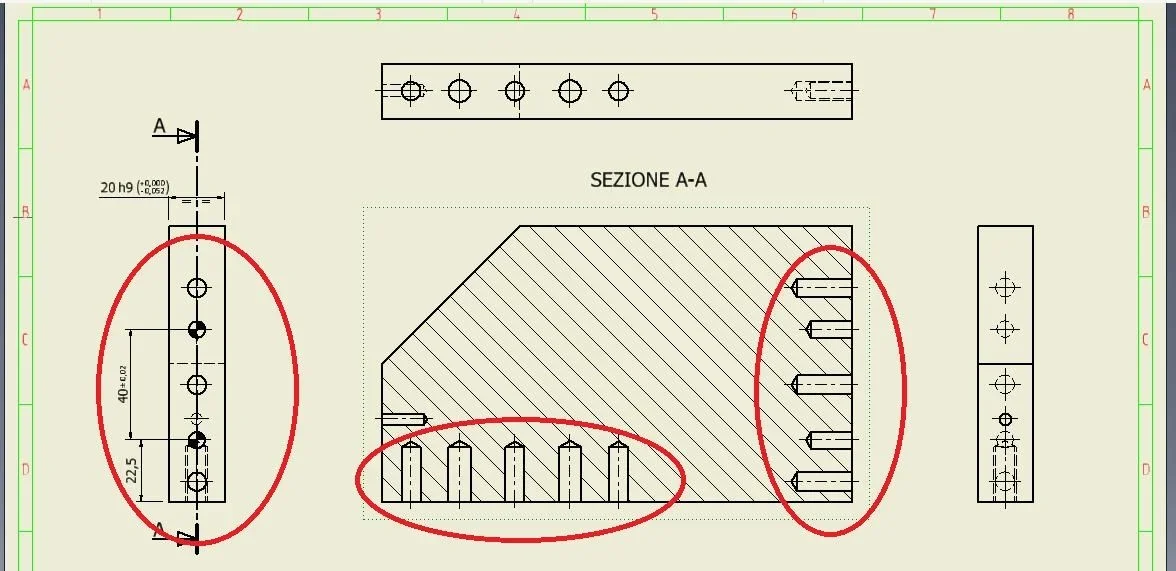
I'm putting on the table an imported model for a customer, being imported threaded holes appear as simple holes.
I ask is there a way that is not to remake the model to show the classic threaded representation in the table? Maybe through cohemtics or some tricks?
thanks to all for any answers.
 

Attachments

  • info1.webp
    info1.webp
    65.5 KB · Views: 4
no, you have to resume the model or do sketches in the table to simulate the thread.
do first to change the model.
 
thanks for the stefano answer,
What do you mean? the model has been imported and the holes are not changeable.. What method should I use?
exists a method to assign the holes with a lot of cosmetics?
 
the fastest way is to use the " thread " command on the cylindrical surface of each hole.
Generally, on imported models, the correct thread cannot put it, if not accepting the error signal that comes to you.
to clarify, if I have a hole that must be m8 and instead it appears smooth, when you do the thread, the prog. proposes you a m9 (the minimum size of a thread that can be realized with that preforo ), to which you can tell him that instead it is a m8, the prog. warns you that you can not do but you accept the same.
in the table, using " hole and thread " indicates the right size (only if you touch the thread ), if you check the size of the thread track ( 3/4 circle ), you will notice a totally wrong share.
the best thing is to make a " thickening/offset " of each hole wall (for m8 thicken 0.5 ), then do what I wrote before and get the correct representation on the table.
 
the fastest way is to use the " thread " command on the cylindrical surface of each hole.
Generally, on imported models, the correct thread cannot put it, if not accepting the error signal that comes to you.
to clarify, if I have a hole that must be m8 and instead it appears smooth, when you do the thread, the prog. proposes you a m9 (the minimum size of a thread that can be realized with that preforo ), to which you can tell him that instead it is a m8, the prog. warns you that you can not do but you accept the same.
in the table, using " hole and thread " indicates the right size (only if you touch the thread ), if you check the size of the thread track ( 3/4 circle ), you will notice a totally wrong share.
the best thing is to make a " thickening/offset " of each hole wall (for m8 thicken 0.5 ), then do what I wrote before and get the correct representation on the table.
Thanks stefano, perfect.. What's resolved.
One question.. when you go to quote gives me the actual size of the thread rather than the usual m8... is it correct?
 
Yes, I did. when I go to quote but it gives me m8.34 instead that m8... is it correct?
 
If you do not use the quota " hole / thread " can be, the linear quota brings you the absolute value, the thickening should be adjusted by 0.17mm, but if you go behind it, you do not finish anymore. (although it would be right to do so)
 

Forum statistics

Threads
44,997
Messages
339,767
Members
4
Latest member
ibt

Members online

No members online now.
Back
Top