You are using an out of date browser. It may not display this or other websites correctly.
You should upgrade or use an alternative browser.
You should upgrade or use an alternative browser.
radio
Guest
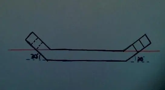
we say better, if you want to represent any element through technical design You must have use at least two views, one front and the other orthogonal at the first, in your case the view from above is the most indicated.good evening to all,I am a new entry..I need some advice on the projection of a plate that has this front view. to represent in true shape the 2 sloping faces can I make a tipping using the plan in red?
Thank you.
n.b. is appreciated, and highly recommended, the presentation for new users; to know how and where you read "small regulation" of this section.
Bye.
maca paca
Guest
Sorry for not presenting,I am not expert on forums. study industrial engineering and I hope to be able to contribute somehow") thanks.
thanks.
However I have already made the 2 short-sighted views and from above, but I'm not sure that to truly represent the tilted faces is a good turn on that floor
thanks.However I have already made the 2 short-sighted views and from above, but I'm not sure that to truly represent the tilted faces is a good turn on that floor
MassiVonWeizen
Guest
the sufficient views are 2: front where quoti angles, thickness, bending points, beams and hole possion compared to a defined plane.
from the top where you have the width, the position of the holes compared to the planes or a symmetry axis and show that there are no, or there are any other geometries.
possibly you can make a view from above with the particular stretch and marking the bending lines, but it is usually required by the workshop or technical office that commissioned the job if it is the case.
I think the auxiliary view over the tilted plane is unnecessary only to quote the holes.
sampom
Guest
No.good evening to all,I am a new entry..I need some advice on the projection of a plate that has this front view. to truly represent the 2 sloping faces I can make a tipping using the red top?
grazie
you have to use a tilted plane for the tilted face (the face itself acts as a plane), and "project" the lines perpendicular to that plane/face
It's true in practice. .I think the auxiliary view over the tilted plane is unnecessary only to quote the holes.
but if they require <<rappresentare delle="" facce="" forma="" inclinate="" la="" vera="">> is "obligatory" the use of auxiliary view (the projection compared to that tilted plane above)</rappresentare>
maca paca
Guest
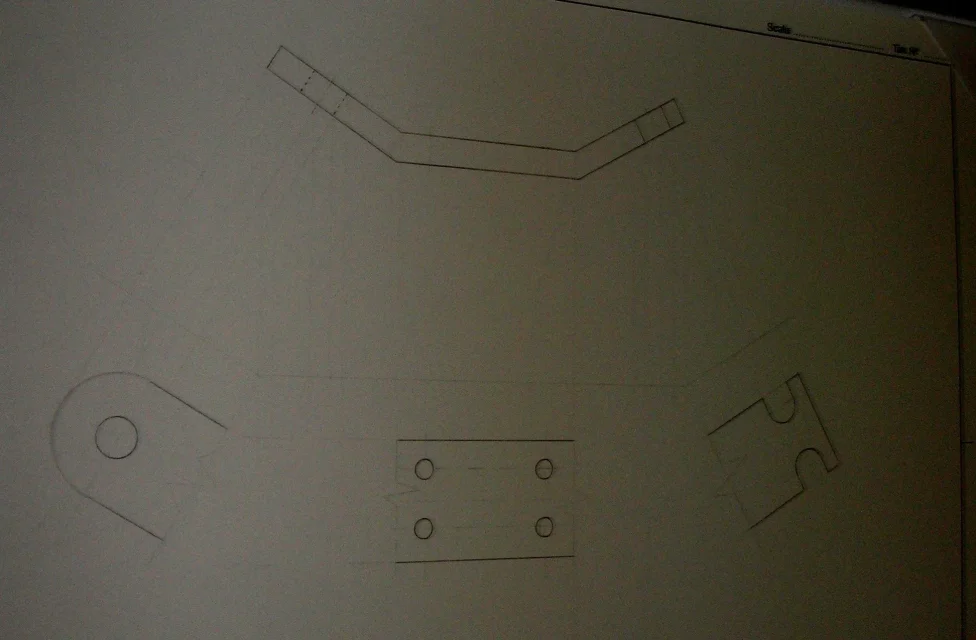
I had designed this way, projecting the significant points with the compass on the red plane and then projecting them into the po. Is this representation correct? I attach a sketch (not accurate) and the original image of the piece I must represent.
) and the original image of the piece I must represent.Attachments


sampom
Guest
Yeah. if you use the compass to "project" the points; the important thing is that the resulting view lies on a "parallel plane" to those tilted faces.. I mean, you see them front.I had designed this way, projecting the significant points with the compass on the red plane and then projecting them into the po. ...is this representation correct? .
Counterblow Hammer
Guest
In my opinion, in this case, we need the view in the plant to quote the 4 central holes, plus two local overturns on the front for quoater the remaining hole and the gaps.I had designed this way, projecting the significant points with the compass on the red plane and then projecting them into the po. Is this representation correct? I attach a sketch (not accurate
to make the furbastries sum up tippings and real plant making the plant of the developed piece (if it was possible clearly).
maca paca
Guest
Counterblow Hammer
Guest
Correct!I decided to do it with auxiliary views because prof prefers them. Is this representation correct with the broken piece in 3 parts? the photo is not very sharp, in correspondence of the breaks there is zigzagata line. Thank you.
to produce it would miss the quotas of the folds, however it is correct!...
maca paca
Guest
Does it hurt if I quote the lengths in the front view?
Counterblow Hammer
Guest
Not even!Does it hurt if I quote the lengths in the front view?
It's the only place you can do that. . .
I think you should draw the axis of the thickness and quote the fold on that axis... .
Forum statistics
ciao