bagiolino
Guest
Hello everyone,
I am faced with a lavour and before I begin I would like to clarify some questions to avoid remaking the drawing several times.
a client gave me a dwg file of a very extended planimetry (complete with level curves and altitudes) that I have to recalcate in revit and then enter my building.
I hoped he importing the revit file would automatically read the quotas and generate the planimetry but so it was not (probably the dwg does not have the quota z).
Now I have to recreate it by point (there will be a thousand: eek") the exact height.
the exact height.
now, quotas range from a minimum of 1000 meters s.l.m. up to 1250.
the design of the building has already been made and with the boss we decided to take as a quota "zero" of the project that of 1000 meters s.l.m. (in fact my plans in revit are listed +98, +101 etc., i.e. +1098, +1101 real).
to avoid problems, is it better to create the planimetry using the "zero" fictitious (so by typing the scaled quotas of 1000 meters)? ?
is it better to create a file apart just for the layout and then import it or do everything in the file where I designed the building? ?
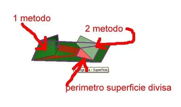
another question, creating the platform under the building I get points where I have to model the ground by adding or removing land, how do I? ?
I hope to be clear and thank you in advance.
Good evening to all!
I am faced with a lavour and before I begin I would like to clarify some questions to avoid remaking the drawing several times.
a client gave me a dwg file of a very extended planimetry (complete with level curves and altitudes) that I have to recalcate in revit and then enter my building.
I hoped he importing the revit file would automatically read the quotas and generate the planimetry but so it was not (probably the dwg does not have the quota z).
Now I have to recreate it by point (there will be a thousand: eek
the exact height.now, quotas range from a minimum of 1000 meters s.l.m. up to 1250.
the design of the building has already been made and with the boss we decided to take as a quota "zero" of the project that of 1000 meters s.l.m. (in fact my plans in revit are listed +98, +101 etc., i.e. +1098, +1101 real).
to avoid problems, is it better to create the planimetry using the "zero" fictitious (so by typing the scaled quotas of 1000 meters)? ?
is it better to create a file apart just for the layout and then import it or do everything in the file where I designed the building? ?
another question, creating the platform under the building I get points where I have to model the ground by adding or removing land, how do I? ?
I hope to be clear and thank you in advance.
Good evening to all!