Powermos
Guest
Bye to all,
I am new to the forum and I am delighted in the mechanics by hobby since by profession I am an electronic ing.
I'm always building a four-fold solar biaxial chaser.
using rhinoceros I created the 3d of the whole structure, I calculated the action of the wind on the surface of the panels, sized the support pole using the resistance module and the type of material and the various bolted unions (I am seeing the calculation and verification of welded unions collecting material to the right and left).
Now I would like to do a numerical analysis to have comfort of the calculations that I have done (as already said I am not an strutturist, I only read several dispenses found on the net) and therefore have a reasonable security that once fitted the system all does not present structural yields (at first the safety, according to the cost since I will have to make realize mechanical details with dimensions of a certain relief from specialized workshops).
for the reasons mentioned above I allowed myself to disturb to ask if someone could recommend an analysis software to the finite elements, possibly free or functional demo for at least 30 days (so as to allow me to do some verification), for structures composed of poles, pipes, plates and other elements like hinges etc... and that allow me to assign the external forces and assign the materials and geometries of the individual details to determine the stresses on my structure so as to see if the maximum dimensioning that I have done is correct. If then geometries could be imported as iges I would also be halfway through the work since I would only export the various groups directly from rhinoceros.
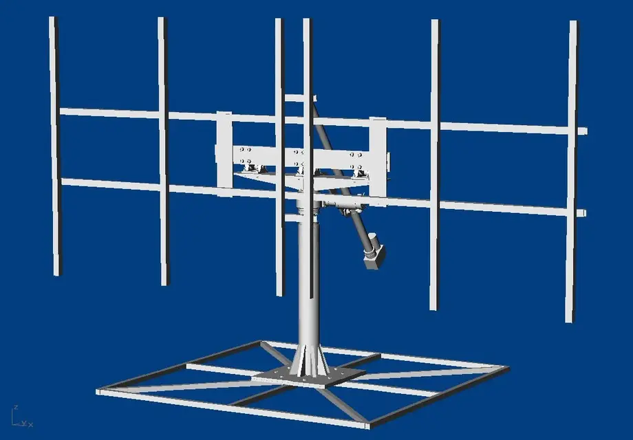
for this purpose, to give an idea of the structure that I should analyze and then realize in practice, I attach a set of screenshots taken from rhinoceros.
since I think that the vision of images does not provide a precise idea of the size of the structure I add some details:
- the support frame of the panels consists of profiles in steel with square section thickness 1.5 mm sadati each other and all supported by the three plates in fe360 from 110 mm wide for 10 mm thick that form the central h of support of the frame. the overall dimensions of the frame are 3.6 m long for a height of 1.6 m. the complete frame of photovoltaic modules, brackets and drawn has a total weight of about 110.64 kg (theoretical weights calculated with the tables of the materials). the three h plates are welded between them and the central plate and bolted through 12 m12 bolts to three snode hinges (of those used for the 100 mm oleopneumatic cylinders) and are used as snodes to tilt the frame respect the horizon.
- the support pole is a fe360 (s235jr) with external diameter 127 mm thickness 8 mm, total height of about 896 mm.
- the base is a square frame that I use essentially to do preliminary tests, for the definitive installation I think I will make a concrete base to prevent the wind if you take it away.
are obviously well-liked suggestions and advice from you mechanical and strutturist experts since you will certainly be able to assess whether my idea was conceived correctly or if there are any underlying vices to correct.
are however welcome examples and the help of chiuque wanted to spend a little time (I know that it is very valuable for all) to help me in this experience (I regret not having entered calculation tests of the structures in the course of graduation, it is a fascinating topic, but I had already several and also I never thought that one day I would have come across in the realization of a mechanical system of this kind...).
thank you in advance for the attention you will want and you will be able to dedicate me.
greetings
♪
I am new to the forum and I am delighted in the mechanics by hobby since by profession I am an electronic ing.
I'm always building a four-fold solar biaxial chaser.
using rhinoceros I created the 3d of the whole structure, I calculated the action of the wind on the surface of the panels, sized the support pole using the resistance module and the type of material and the various bolted unions (I am seeing the calculation and verification of welded unions collecting material to the right and left).
Now I would like to do a numerical analysis to have comfort of the calculations that I have done (as already said I am not an strutturist, I only read several dispenses found on the net) and therefore have a reasonable security that once fitted the system all does not present structural yields (at first the safety, according to the cost since I will have to make realize mechanical details with dimensions of a certain relief from specialized workshops).
for the reasons mentioned above I allowed myself to disturb to ask if someone could recommend an analysis software to the finite elements, possibly free or functional demo for at least 30 days (so as to allow me to do some verification), for structures composed of poles, pipes, plates and other elements like hinges etc... and that allow me to assign the external forces and assign the materials and geometries of the individual details to determine the stresses on my structure so as to see if the maximum dimensioning that I have done is correct. If then geometries could be imported as iges I would also be halfway through the work since I would only export the various groups directly from rhinoceros.
for this purpose, to give an idea of the structure that I should analyze and then realize in practice, I attach a set of screenshots taken from rhinoceros.
since I think that the vision of images does not provide a precise idea of the size of the structure I add some details:
- the support frame of the panels consists of profiles in steel with square section thickness 1.5 mm sadati each other and all supported by the three plates in fe360 from 110 mm wide for 10 mm thick that form the central h of support of the frame. the overall dimensions of the frame are 3.6 m long for a height of 1.6 m. the complete frame of photovoltaic modules, brackets and drawn has a total weight of about 110.64 kg (theoretical weights calculated with the tables of the materials). the three h plates are welded between them and the central plate and bolted through 12 m12 bolts to three snode hinges (of those used for the 100 mm oleopneumatic cylinders) and are used as snodes to tilt the frame respect the horizon.
- the support pole is a fe360 (s235jr) with external diameter 127 mm thickness 8 mm, total height of about 896 mm.
- the base is a square frame that I use essentially to do preliminary tests, for the definitive installation I think I will make a concrete base to prevent the wind if you take it away.
are obviously well-liked suggestions and advice from you mechanical and strutturist experts since you will certainly be able to assess whether my idea was conceived correctly or if there are any underlying vices to correct.
are however welcome examples and the help of chiuque wanted to spend a little time (I know that it is very valuable for all) to help me in this experience (I regret not having entered calculation tests of the structures in the course of graduation, it is a fascinating topic, but I had already several and also I never thought that one day I would have come across in the realization of a mechanical system of this kind...).
thank you in advance for the attention you will want and you will be able to dedicate me.
greetings
♪


") that many technicians should possess.
that many technicians should possess.