meccanicamg
Guest
Thank you.cz=combined zones or common areas
czr=combined zone rotational only (not our case)
sim=simultaneous rerequirement (and possibly a sim1,sim2,... -if more sim-)
Thank you.cz=combined zones or common areas
czr=combined zone rotational only (not our case)
sim=simultaneous rerequirement (and possibly a sim1,sim2,... -if more sim-)
I don't agree on the first part. if I give a flatness of 0.005 to each face and a parallelism of 0.005 between the two nothing forbids me that between the two faces there is a difference of any level, that can be of a millimeter, of 100 mm or, absurdly, as I have written above, of a kilometer. the two faces can always be perfectly flat and perfectly parallel.just to contextualize the issue with numbers, if we want to get a "complanarity" between the two red surfaces of the first post of ±0,015 we will have to define a planarite on the single face of ±0,005 and a parallelismo between the two surfaces of ±0,005.
imagining that a surface will be stunned of +0,005 and the other -0,005 and that they are not parallel of 0.005 we will have a maximum extremity of 0.015.View attachment 68199the "complanation" symbol does not exist in gps.
iso 8015 indicates that even if we put the "planar" on multiple surfaces, it is indicated that the flatness is reported separately (explained in iso 1101:2017.... because of course it leaves doubt). if you put sz we will emphasize "separate zones".
a little more messed up is the cz that indicates concatenate zones. This feature allows in a non-independent way to group surfaces and define gps.
probably should allow with only one Planners to define that all surfaces bound by cz are from top to bottom planes equal to tolerance.
but it is a new and unclear concept.View attachment 68200this thanks to the iso 5458 of 2018 that allows to group "things" also against previous norms.
So the real problem is: if we design and design are not updated to the latest standards, how can we expect them to understand what to do in the workshop?
I would continue with the two separate directions (parallel and planar) or even the written note for extended to stupid proof.
with all these new standards you can no longer read the drawings.
for each plan you have to give the exact quota from a reference, that's what doesn't make you agree. That's what the norm says. the exact quota puts in a rectangle.I don't agree on the first part. if I give a flatness of 0.005 to each face and a parallelism of 0.005 between the two nothing forbids me that between the two faces there is a difference of any level, that can be of a millimeter, of 100 mm or, absurdly, as I have written above, of a kilometer. the two faces can always be perfectly flat and perfectly parallel.
I did not know the concept of the cz, but this seems to me already much more exhaustive: If I didn't get it wrong, he says that the three faces indicated in the example must be considered a single face, which would suit me. We must see how many millers and rectifiers there are who know him. . .
as to the written note "idiot proof" I agree that it is often the safest solution.
tolerances have been studied and inserted in the drawings, even to prevent the performer from feeling compelled to perform a precise dimension as much as possible, when it is not necessary.Good evening, everyone.
I would like to ask if someone can enlighten me on a matter of this kind: I have a piece like that in the figure below. in this particular the two faces you see colored red must be perfectly round (let's say within a couple of cents). These are faces that will be rectified, but for obvious reasons cannot be rectified together. to put tolerances of flatness on both surfaces is not enough, because tolerance says that they must be flat but not necessarycomplanaries. I could put narrow torches on the lower or upper surface, but that's exactly what I don't want to do because this distance is really unimportant and I'd win who does the piece to a precision that won't feel at all.
summing up: I care that the two faces are flat and flat, but the distance from the faces I care little. What form tolerances should I put on the design?
Thank you in advance.View attachment 68184
 www.tec-ease.com
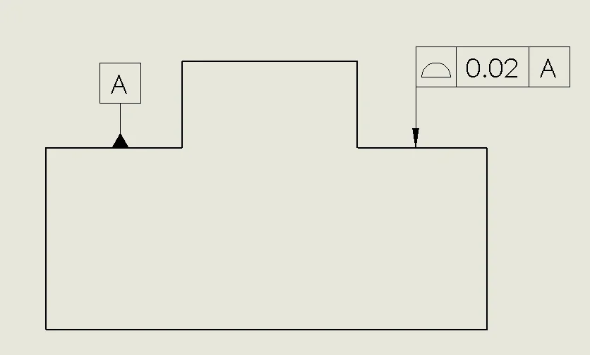
depends on the system you use. iso gps or asme 14.5?I have clashed several times on this. on indication of a supplier I discovered these:
from which the correct gd&t symbol would seem that of the profile using a construction line to 'group' the surfacesGD&T Tip - For Coplanarity Use Profile
Tec-Ease offers GD&T training, course material, teacher aids and reference charts.
What do you say?
Andrea