
• This forum is the machine-generated translation of www.cad3d.it/forum1 - the Italian design community. Several terms are not translated correctly.

transition constraint problem

  • Thread starter Thread starter Daniacm27
  • Start date Start date

Daniacm27

Guest
Good evening, I'm "new" on inventor and I'm trying to make a 2-axis trolley. the problem is mainly one, to take to my cart a curve, thus simulating the bike that should have. I managed to do it with 1 axis, but if I do 2, then the game doesn't work anymore and I'm not succeeding in running it. the situation is practically this:
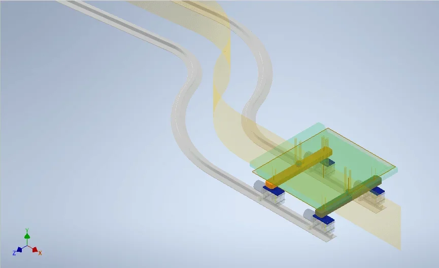
Immagine.webp Now, what I did was to assign the transient bond to the central plane of the rail in figure, coupled with superficial extrusions made on the two axes (let the ones present at the center of the entire structure and the tiny ones present on the 4 wheels) . However at the end of the straight stretch, when I try to animate everything, I get the error message.
Whereas the two axes are inserted within the transparent and free base to rotate around your center, what could be the mistake? Could someone please help me?
Attached, for those who want to help me, I also leave you a .zip file with all the drawings, so maybe you can better understand the possible error. Thank you very much in advance
 

Attachments

You have to remove the two corner constraints, but it's not enough yet.
he can't complete the route, he gets to overcome with the first axis the double s, then he stops.
However you have the sketches that generate the under-invited processing, with deleted references and inserted with the terna of the plans to muzzo.
if you do not learn to have the most ordered primitives, it is premature to do these movements.
In addition, the transient bond, together with the symmetrical, is a little uncertain, for years it is.
 
You are right and I apologize for this, but unfortunately I sketched the job quickly and fury and it is hardly that I use inventor. I am aware however of the problem linked to the constraints but unfortunately I have to do the thesis and they have given me to use inventor from one day to another... and the key to everything is precisely to understand whether this path is feasible at real or not, because for the project that I have to do, unfortunately I need to understand first of all this and then possibly change curves and other. if there is some way you know to represent everything, even with another software, I would be grateful
 
If I have to give judgment on that system, without knowing what you have to do, I would tell you that, in reality, it can't work.
It is important to know whether it is a mad or motorized cart and, if motorized, how and where.
It is not just a software problem, maybe you can set constraints that allow you to complete the path, but they are not the ones you will actually have, like driving the cart through the central surface that, in reality, does not exist.
that handling scheme is usually solved with a reversed birotaia, stuffed to the floor, with the crazy and pivoting wheels, but it is not said to do to your case.
 
I have to move a load of about 7 tons basically, in 2 different jobs. the problem is the encumbrances, because that path is the one that gets married to what I have to do. at least this is what I managed to think, maybe there is a different solution. Of course, on that cart, there are looms to support everything, but I still needed to figure out whether for such a path, with a narrow curve, everything was feasible. the cart is motorized, with 1 gearboxes to the height of the wheels simply. that is those wheels are from catalog and with the characteristics to level of weight and transmissible pairs, that it serves to me.
 
not every wheel, but a wheel is motorized through a gearbox, which in general will apply a couple that can move the whole system. consider that those wheels are able to support up to 3.5 t each, while my load on each wheel will be about 2.5 (approximately for excess). then the choice of the engine we say that it is secondary, in the sense that I will need to have before the most accurate data in terms of weight, forces and pairs, but basic that whole mechanism is from catalog, i.e. I speak to you of the reducing group+ruote, so you should be able to move. then, however, the problem of the path that engineeringly is not a nice path. But if you want, I'll send you an image of the environment where you can put it all in, so if you like, you tell me if you think it's feasible and at the same time if you have any idea/suggestion to give me
 
I don't know how to move those loads, but they're sorts of handling I know, if you want to send me a m.p.
I should like to remind you that the problem is not the constraints to be given in the cad, but the choice of the most appropriate solution, this does not seem so.
 

Forum statistics

Threads
44,997
Messages
339,767
Members
4
Latest member
ibt

Members online

No members online now.
Back
Top