You are using an out of date browser. It may not display this or other websites correctly.
You should upgrade or use an alternative browser.
You should upgrade or use an alternative browser.

gfrank
Guest
... you read this discussion:http://www.cad3d.it/forum1/showthread.php?t=3407
gfrank
Guest
the family of departure to use is "structural metric routes"
in the family must be inserted lines that represent the upper and lower pillar, selecting the appropriate icon "top current (or lower) and then draw the line with the drawing tool.
the same must be done for the "anime" (tilted beams) with the instrument "soul", drawing lines that need.
in practice the "trave pattern"
once imported into the design, they activate "the property" with the various management parameters
gfrank
Guest
the above beam always has the upper and lower parallel mount, and the "anime" have a constant step.
if you need to make a rake on the tip, you must use a family of beams with:
1- two horizontal plane, upper and lower, on which to draw through extrusions on the path the upper and lower beams
2- a vertical plane, passing in halfway to the longitudinal profile of the beams referred to in point 1 on which to draw the souls (tilted beams) always by extrusions on path
3 - so many vertical planes, orthogonal to that of point 2, which, at the intersection with horizontal planes, determine the beginning and end positions of the souls
all plans must be connected with appropriate management parameters (lengths) to determine the distances (lengths) necessary to:
- initial and final distance between the beams
- distance of souls (pass)
which if associated with related functions (e.g. step = 1/3 distance between beams) are automatically managed
add also the type of beam and souls, as well as the material
Last edited:
kubbah
Guest
Tristan
Guest
Yes, if you find it; did you look for it?Is it possible to use a family already ready?
kubbah
Guest
There are beams. but I would like to understand how to draw it on these sloping surfaces. .
gfrank
Guest
creates a new familyIs it possible to use a family already ready?
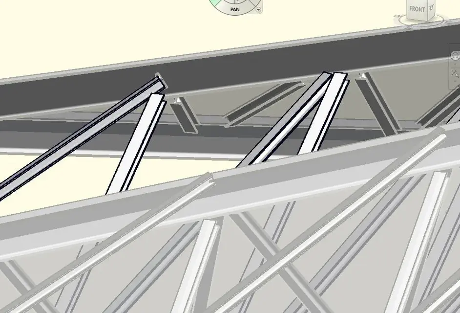
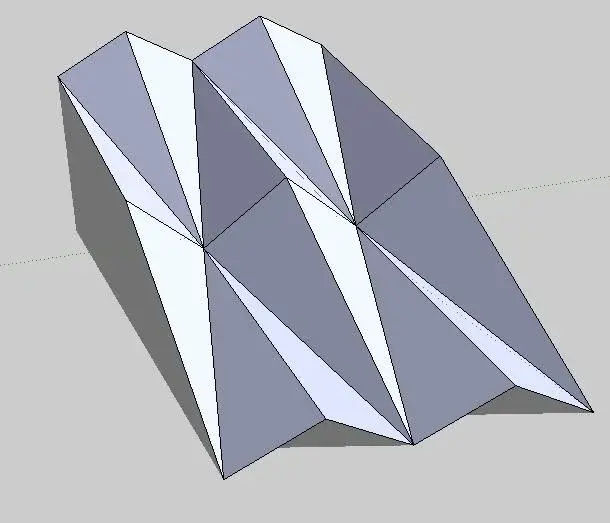
How do I draw a reticular beam that follows these forms - tilted planes (Annex) ? what is the best way to do it?
parts from a surface that defines the shape, as from your attachment.
in the top of the surface, insert the beams.
assigns parameters (length) to all surface edges and (material) to beams
make the surface invisible.
kubbah
Guest
instead for the inclined rods of the reticolar beam (to speak of those that combine the lower current to the upper one)
Thank you.
(p.s. is the window that makes me design in a perpendicular way to the work plan or in 2011 they removed it? )
Thank you.
(p.s. is the window that makes me design in a perpendicular way to the work plan or in 2011 they removed it? )
gfrank
Guest
use of reference plans
kubbah
Guest
but the reference plans yes, I am using to draw us
but to have a perpendicular view on the reference floor?
instead to draw the details of connection between the various beams?
Should I use revit structure?
but to have a perpendicular view on the reference floor?
instead to draw the details of connection between the various beams?
Should I use revit structure?
gfrank
Guest
1 - with the view command, do a perpendicular section on the reference plane and use that
2a - creates specific families (e.g. boards)
2b - if you are interested only as details (in detail views) you can use 2d drawings to be inserted in such views
2a - creates specific families (e.g. boards)
2b - if you are interested only as details (in detail views) you can use 2d drawings to be inserted in such views