• This forum is the machine-generated translation of www.cad3d.it/forum1 - the Italian design community. Several terms are not translated correctly.

use of one part to model another

  • Thread starter Thread starter Stefano_68
  • Start date Start date

Stefano_68

Guest
Good morning to all,
I'm starting to study inventor recently trying to develop design procedures.
the problem that I put on is as follows:
I shaped a part of a set, for example a simple parallelepiped with a hole.
now I would like to model another part, say a second parallelepipedo, which also has a hole "passante" with the first,
how do I impose the work to change the first hole (position, diameter, shape....) is also updated the other hole on the second part?
I hope to be explained I thank you for the attention.

Have a good day!
 
create a new part, derive the first in the second and do the additional jobs you need.
 
good morning technomodel and thanks for the answer.
I performed this operation:
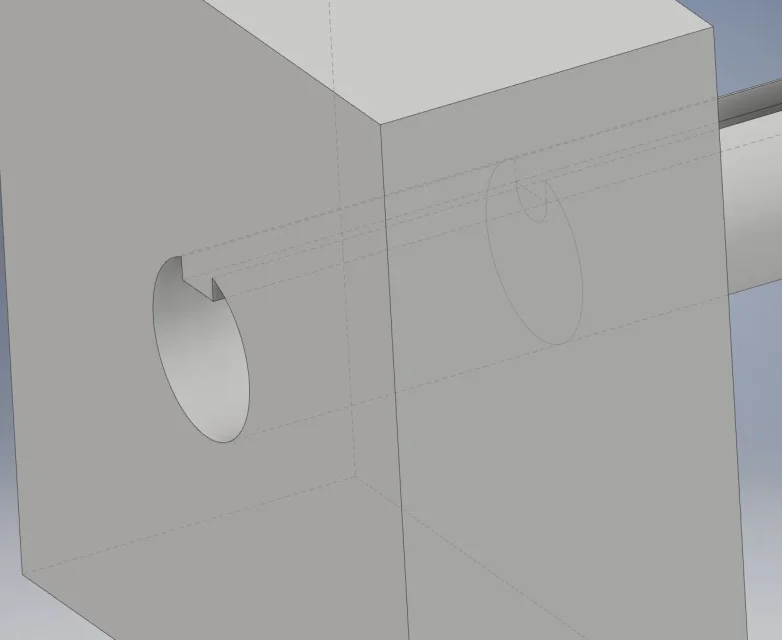
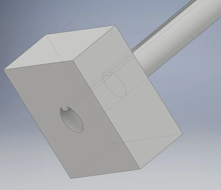
- created a first part, a cylinder with a groove;
- created a second part, a parallelepipedo, in which I derived the first part;
- projected the geometry of the first on the second (the cylinder section with groove) and with such sketch I created the subtraction solid creating a hole in which the grooved cylinder passed;
I would now like to change the type of groove on the first part and make that change to the hole of the second part.
How do I do that?Parte derivata.webp
 
simply do the change, then update the second part and the change also affects it.
 
Parte derivata_01.webpmodification made on the first part (the cylinder),
but, despite having also closed and reopened the file of the second part, the modification was not made.
Where am I wrong?
Thanks again
 
also serves the part you derived.
the file you posted has only one solid, is it so or is it caused by the lack of drift?
 
some suggestions:
- for such processing you may also avoid deriving the whole solid but only derive the sketch that interests you. then use it by projecting geometry to create the sketch of the seat to be obtained.

- another way is to derive the solid and use that for a boolean subtraction operation.in that way any modification you make to the main solid the meeting place on the obtained seat.

- Watch how you make changes, if you have a seat with live edges then go change it by inserting rays you can have problems. This is because it modifies the entities of the sketch by adding others, same thing if you delete some.
the same goes if you create a sketch in the primary part that is just a projection of a face and go to derive it.
If you change that I do by adding entities, like a ray, then you also have to enter the sketch and project what previously was missing.
 
I'll try to practice following your advice.
thanks for the availability and good day
 

Forum statistics

Threads
44,997
Messages
339,767
Members
4
Latest member
ibt

Members online

No members online now.
Back
Top