Aurora88
Guest
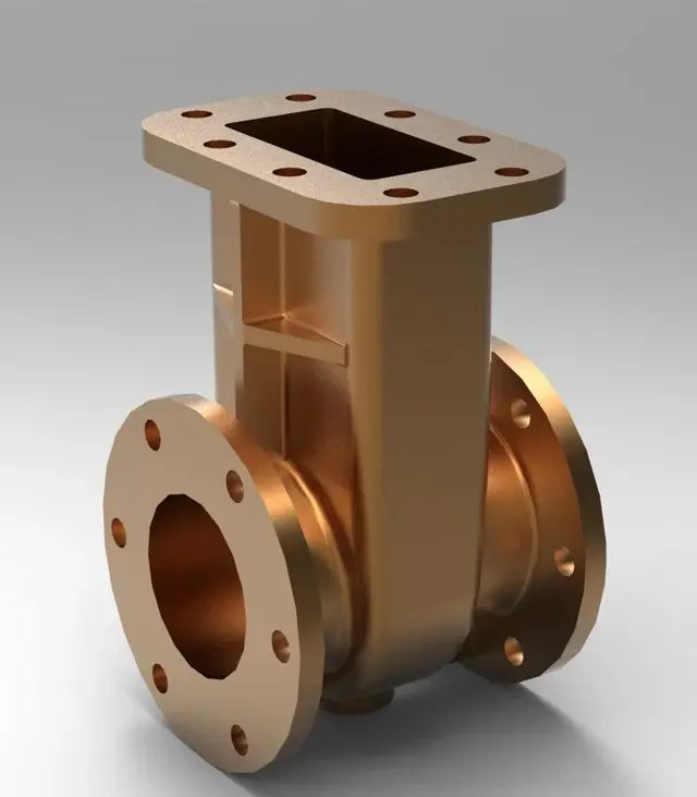
hi to everyone, sorry the question will be for you quite banal, I have a problem, I have to reproduce a valve to saracinesca, I have managed to do everything (so also the "stantuffo" inside the tree and the snail)
less than the case because I can't figure out what kind of functions I could use. . you will have already realized that I am not very good with the program but I just started using it... I attach an image and thank you in advance
less than the case because I can't figure out what kind of functions I could use. . you will have already realized that I am not very good with the program but I just started using it... I attach an image and thank you in advance


")