AngeloB
Guest
Hello, everyone.
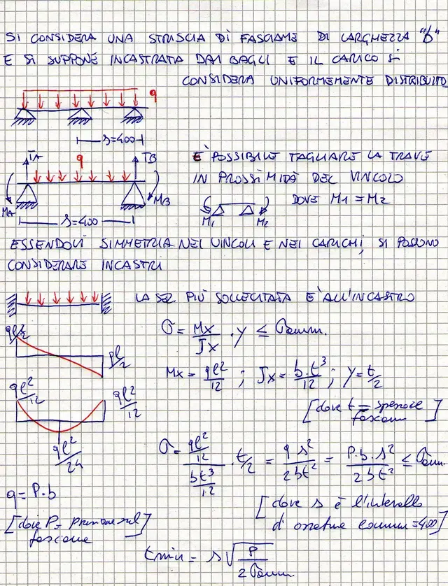
I have to understand if a metal grille is able to withstand a concentrated load (a crane).
by grid I mean a metal structure composed of longitudinal and transverse beams, covered by a sheet.
I solve the calculation with the fem, but I would like to compare my results with someone.
who is available?
Hi.