• This forum is the machine-generated translation of www.cad3d.it/forum1 - the Italian design community. Several terms are not translated correctly.

vine-corona gear teething test with inventor

  • Thread starter Thread starter mikelocke
  • Start date Start date

mikelocke

Guest
Good evening,
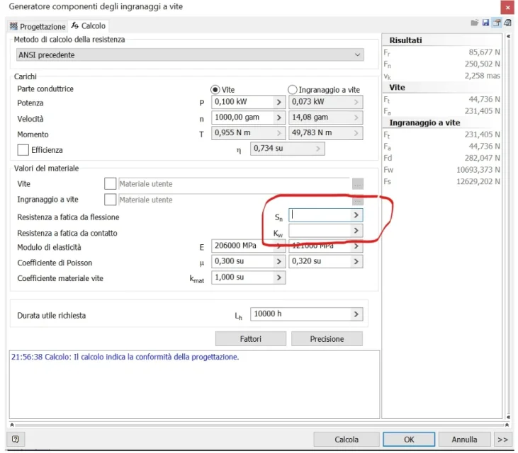
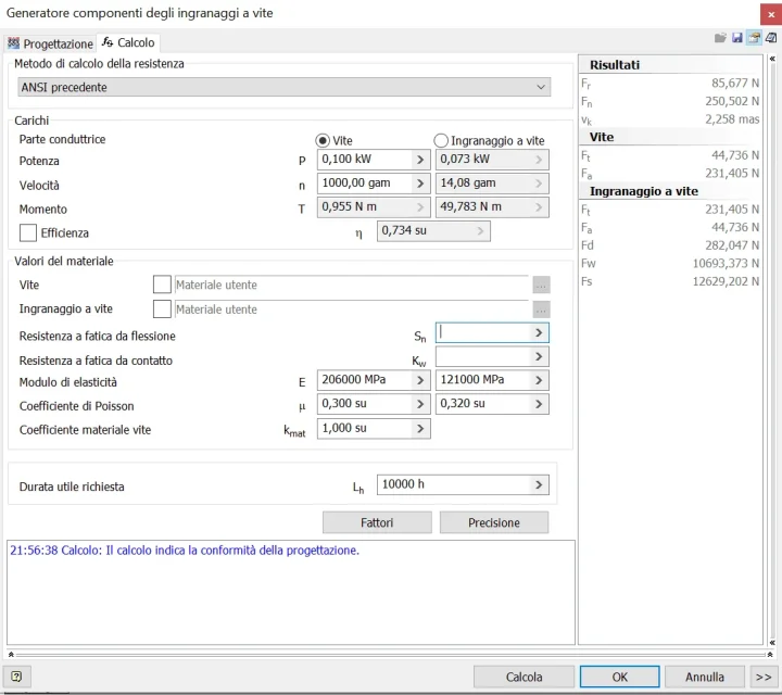
are in the grip with the verification of the toothing of the crown with the method proposed in the generator of screw gears of inventor, I would like to assign a material to the crown not belonging to the list present in the form, I saw that it is possible to do it and perform the verification as long as to assign the new values of sn and kw, the question is.. where can I find these values?to what do they report? or how can I obtain them taking into account that the crown material will be a steel, type c45 reclaimed, c45 normalized?
I noticed that they are not the same values in the cylindrical gear module see figure below:1571690316795.webpThank you for your cooperation

Michael
1571689086019.webp
 

Attachments

  • 1571688839226.webp
    1571688839226.webp
    63.9 KB · Views: 5
Good evening,
are in the grip with the verification of the toothing of the crown with the method proposed in the generator of screw gears of inventor, I would like to assign a material to the crown not belonging to the list present in the form, I saw that it is possible to do it and perform the verification as long as to assign the new values of sn and kw, the question is.. where can I find these values?to what do they report? or how can I obtain them taking into account that the crown material will be a steel, type c45 reclaimed, c45 normalized?
I noticed that they are not the same values in the cylindrical gear module see figure below:View attachment 54903Thank you for your cooperation
Michael
View attachment 54902
Bye. the values of the standard mentioned by you are different from sh and s of cylindrical or conical gears regarding the wheel.
regarding the screw should be quite the same.
instead of using "custom material" see that values provide you with a cementing steel and post the numbers we are considering.
the thing you can do is look for the values of materials on the niemann.
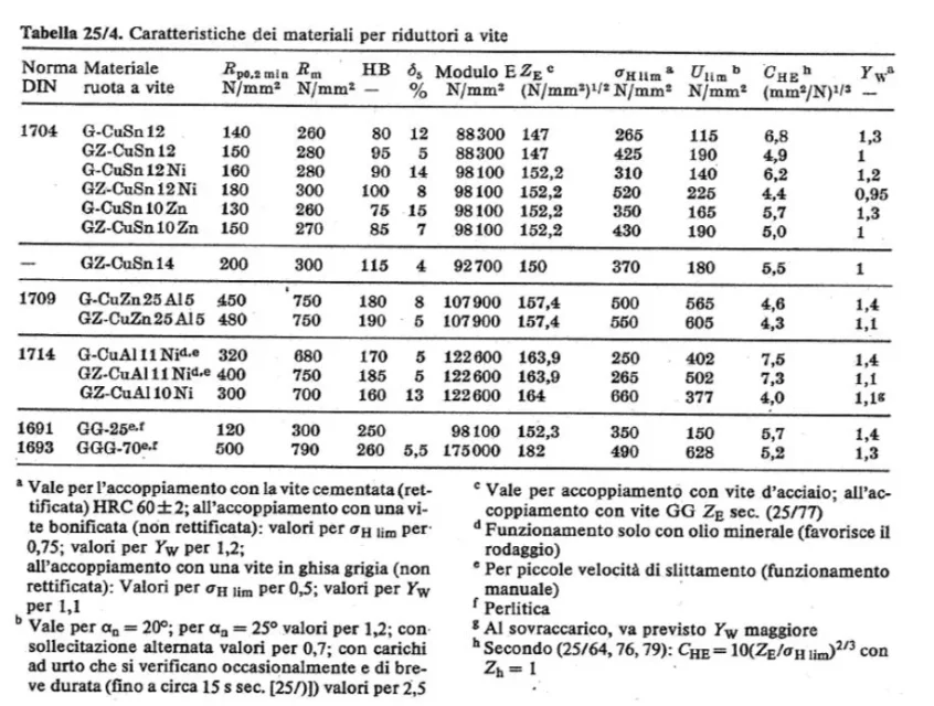
for the wheel goes:Screenshot_20191022_195930.webpsome explanations you find on the portal autodesk qui per esempio.
 
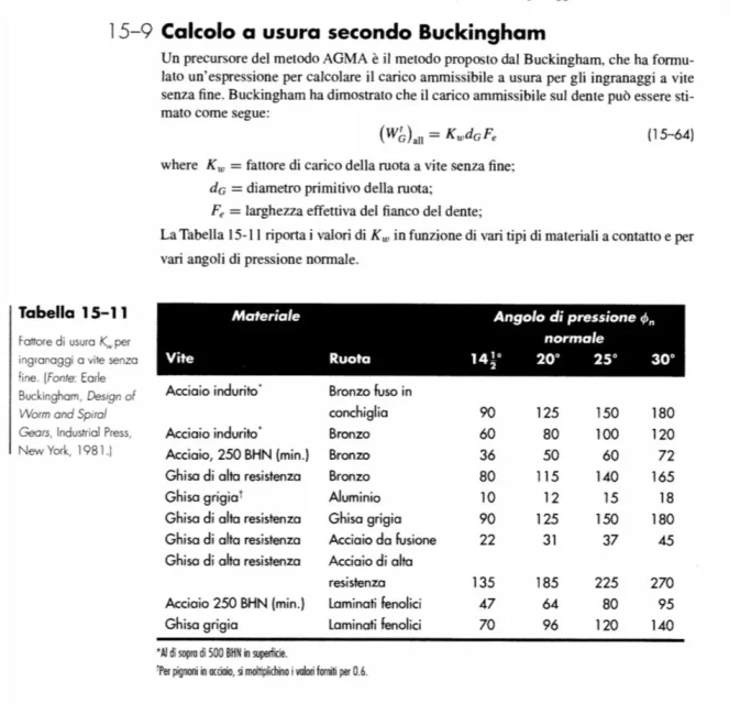
it seems that the data only of the screw does not exist because in essence it is the wheel that wears and yields that it is in an increasingly weak material of the screw. There are values for the wear of the coupling of two materials on the sighley that I attach to you.
Screenshot_20191022_203015.webp
 
looking at the inventor's calculation module asks you the two parameters that you find in the tables that I reported to you that take into consideration the couple of materials.
 
Good evening,
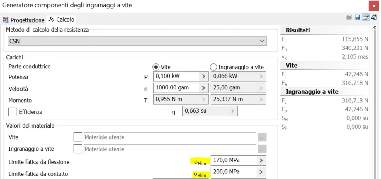
first of all I thank for the kind availability.. returning to the speech of the verification of the crown, I noticed that the generator of gears of inventor allows verification also with a different method, called csn (photo attached) that follows the norm 6336-5.
In the meantime, what of the two methods is preferable? Are there substantial differences?1571782959677.webpin the csn method are present the two parameters sigmaflim and sigmahlim.
As in the inventor screw gear generator is not expected to assign to the crown no steel, I decided to extrapolate sigmaflim and sigmahlim from the module dedicated to cylindrical gears. Does that make sense?
Therefore for the definition of the new material of the crown, I must only copy the values of the steel of my interest, present in the cylindrical gear module and return them to the screw gear module.
I have the need to verify crowns made of steel c45 bon ,c45 norm and an untied steel 38nicrmo3.
the values of the sigma of the first two are present in inventor, while there is nothing for the 38nicrmo3 .
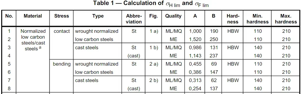
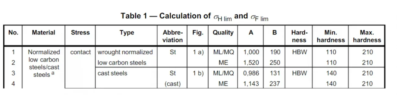
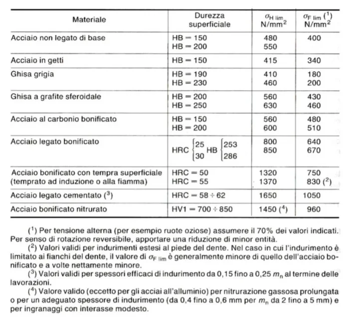
peeking in the forum, I read an old post about how to extract the values of sigmaflim and sigmahlim through the formula ax+b present in norm 6336-5.
as a verification I tried to calculate the sigma for the c45 and then compare them with the values of inventor and with my surprise I did not find feedback. .they are quite different..How come there are corrective factors to consider? not just use the formula?
sigmaflim and sigmahlim are the limit tensions (to infinite life reversal ?hypotizzo), so I imagine that inventor can draw a hypothetical wholer digram based on the yielding load and the sigma..
the verification of the gears with this method is satisfied by inserting the two sigma and the duration lh for a given nominal torque value present at the crown.. but if I have to verify the teething to a torque, that is, quite greater than the nominal torque, but applied for a short time, how do I have to behave with the verification?
I apologize if I stretched out a bit. I greet you and thank you again.
greetings
Michael
 
inventor used it years ago and I found that the internal definitions have always remained behind the current norms, because as a rule there are different revisions with even heavy corrections.

using iso6335 is the most complete and correct rule that you can use for gear analysis and as such admits the values of fatigue and wear tensions from iso6336-5 as you did and if it is a good quality material a reclaimed c45 will have an indication of a calledgmahim=540mp e una gmaflim=210mp. I am convinced that inventor, if using lower numbers is using values that are related to the old one.
the evaluation and therefore the sizing of a helical vsf/roll for peak loads is normally carried out by evaluating the intermittent service, i.e. if your reducer is subjected to pair of "stall" not in continuous service s1 but for 10% you must see to change the parameter corresponding to the service factor (I don't remember if inventor has it) so that the check to wear and contact temperature between the teeth.
In theory if you use the iso6336 you should also use the iso tr and consider lubrication and real temperatures, while with the bs 721-2 you absolutely cannot do the verification you want, as well as having a high oversized.
just to give you an idea see this post.
 
Good evening,
then recapitulating...if I use the csn method I realize a more accurate verification on gearing.
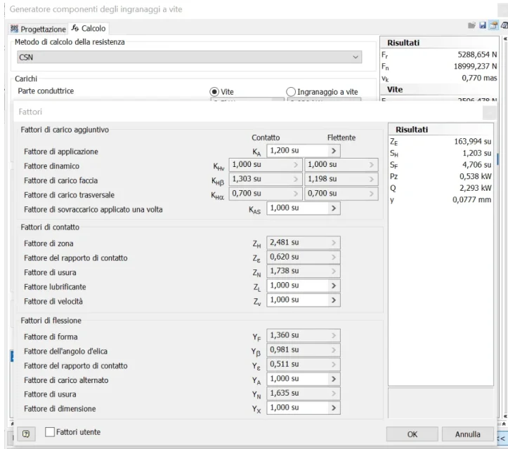
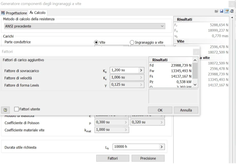
In fact, the factors at stake are much more than the anxiety as seen in the photo.
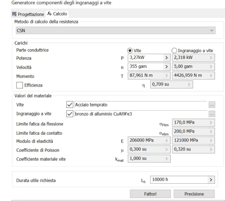
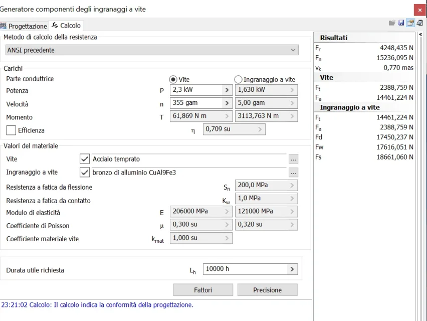
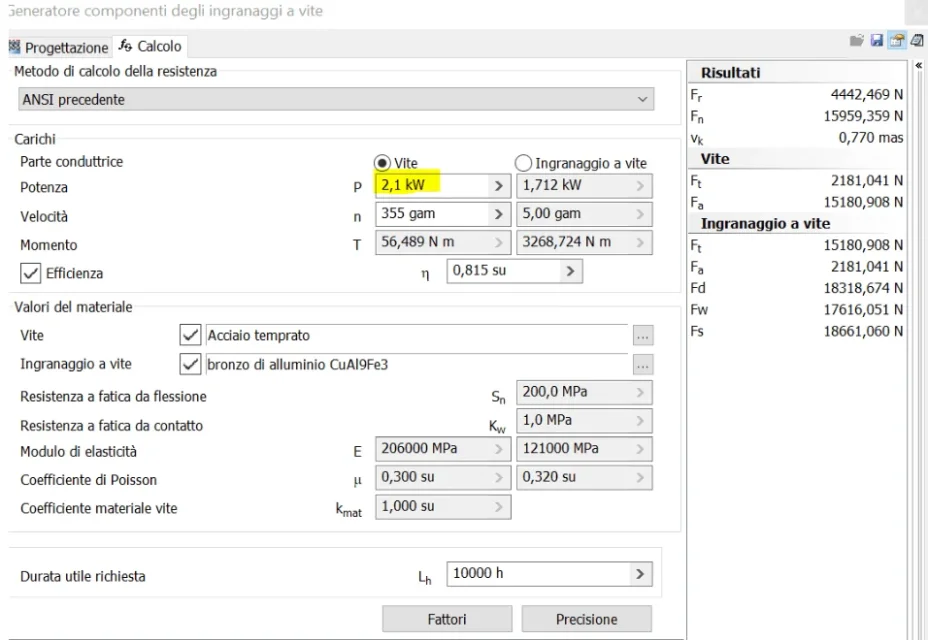
By the way, the service factor you mentioned for checking the torque could be the kas?e how would it be modified? do I have to intervene also on the required service life lh?csn method:1571864230895.webpmethod:1571864611199.webpI also have to say that they lead to two quite different results, the csn method allows to push higher with the powers, results?limit power with the csn method:1571865090567.webplimit power with the anxiety method:1571865822350.webpIn conclusion, for the calculation of sigmahlim and sigmaflim I noticed that the inventor values are higher than those obtained using the norm, for example for the normalized inventor c45 reports:1571866151990.webpsigmahlim =430 and sigmaflim = 356 mpa..both the values are higher than the tabulate yield... is it possible? ? ?
with the calculation following the norm. .1571866955319.webpI get,take hbw at minimum to 110(precautionary condition):
sigmahlim= 1*110+190= 300 mpa;
sigmaflim=0,455*110+110=160 mpa;
are rather distant values from those of inventor.. .
setting hbw to maximum..210 I would arrive to :
sigmahlim = 210+210=420 mpa
sigmaflim=0,455*210+210= 305 mpa, and at the bending are still distant from the value 356, moreover. .use the maximum hardness does not seem to me the correct choice. .if anything to be in favor of safety should be set to the minimum value.I say well? at this point I do not know how to interpret the values of inventor... what do you think?
Thank you again for your help.. .
Michael
 

Attachments

  • 1571864786900.webp
    1571864786900.webp
    48.3 KB · Views: 1
  • 1571866417051.webp
    1571866417051.webp
    32.8 KB · Views: 2
definitely cns has more parameters and as I told you before follows the iso6336 so you have many more parameters because the norm is more performing. the ansi-agma rule is more generic and many things and parameters do not consider them.
Therefore at the same geometric parameters, cns considers all the lubrication parameters, which normally give good operating conditions and therefore can be pushed stronger to the limit of the lubrication parameters.
l10h are operating hours and if there are no other parameters it is possible to study for example a very higher incoming power but for a very low number of hours, for example l10h= 10ore. In this way wear is very low and the contact pressure can rise creating a lot of heat, but being for a short time.... is well different from the reducer that always turns under chearic house.

If you look at the calculation cards you will see that for the screw you do not talk about sigmah or sigmaf, there are no values and are only indicated for the underform wheel of sn and kw....and are like the values I had attached to you in previous posts and depends on the coupling of the two materials.

the sigmahlim and sigmaflim speech depends on the minimum/maximum hardness even to the type of quality, in fact you have ml/mq that are different from the quality me. depends on certificates, experiences and applications, so it is not said that you use the same values. I suggest you remake the accounts a*x+b because they are not all right numbers.
other than his control are the values that gave the old noma uni8862 or similar that obviously do not go mixed....even if I have the doubt that inventor declares iso6336 but does not use the numbers of the norm but makes them come with conversions.Screenshot_20191024_201001.webpthe ka factor is the application coefficient and serves if greater than 1 to determine the peak conditions at maximum torque which is the multiplied ka.
for the verification of the reducer however it is carried out ka=1 and it is used the ka true greater than one to verify the maximum conditions of wear, sagging and breaking but not the transmitted forces that follow ka=1.
correctly using an intermittent service less than 100% fact decreases actual lh10 compared to the nominal.
 
I'm dealing with and I think that the kas factor is what defines the thing once happens if it goes to a nominal pair multiplied kas. You should check on the inventor's guide and see what he explains.

instead the ka is the classic identification of the burden of the application of the load and covers all the factors of verification.
 
Good morning, I always thank you for the kind collaboration, I decided to let go of the verification made with inventor as from ambiguous results. I noticed that from different results to equal parameters,change only the verse of the propeller (dx or sx).. which does not make much sense. .
at this point I wanted to deal with the verification following the procedure described by the norms and I saw that those to follow are practically two:
the iso/tr 14521o the iso 3996.
My main problem is to find something that occurs to me the gear having both screw and wheel in steel.. where can I find these rules?
Thank you very much
Michael
 
you can find for consultation in some specialized library, in the universities could be otherwise it should be bought on the site one.
you can try kisssoft which is really an excellent calculation program. you can have a demo and a trial version....so you can try it.
 

Forum statistics

Threads
44,997
Messages
339,767
Members
4
Latest member
ibt

Members online

No members online now.
Back
Top