• This forum is the machine-generated translation of www.cad3d.it/forum1 - the Italian design community. Several terms are not translated correctly.

solids and/or extrusion surfaces

  • Thread starter Thread starter brikki86
  • Start date Start date

brikki86

Guest
Hello, guys, excuse me if I'm back breaking up and asking for your help... .
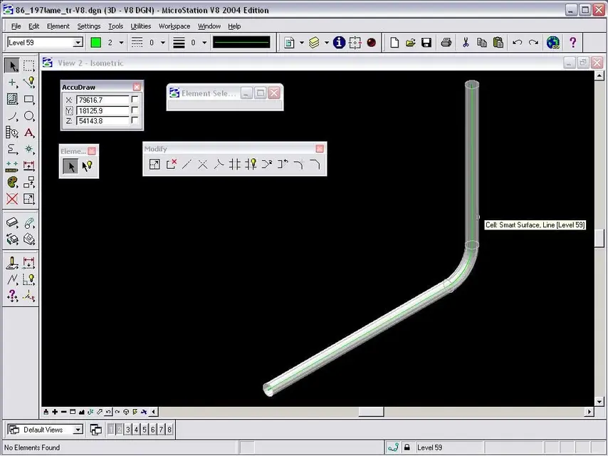
I was flying to ask you if you knew some setting to make sure that the command in question does not give problems...in the sense that, having to draw electric cables also bent, I wanted to use that command as an extrusion of a circle on a folded line, but it does not create a nice uniform cylinder, but rather a tighter sausage in some points and wider in others (you also deform the straight part). This happens to me at work, while a friend of mine is perfect... I attach the image of how it comes to him before accepting the change.
can it be that the problem is given by some settling? !
Thanks again guys!! ! ! !
Then I also put my "buckle" cylinder on it.
 

Attachments

  • Immagine estrusione percorso.webp
    Immagine estrusione percorso.webp
    36.4 KB · Views: 21
boh, do you want to get this? (see attachment)
if it is so to me it comes perfectly to the first hit, I also made sure to highlight the central axis.
Hi.
 

Attachments

  • tubo.webp
    tubo.webp
    49.7 KB · Views: 16
apart from the fact that brikki is a solid and not a surface (then different tools and behaviors), there is to say that working, by his luck, with a more updated version of yours, can, without complications, use the option "internal-toll" for a fast and error-free modeling.

with regard to the "salsicce", without seeing them it is impossible to suggest the best passage from the sausage to the electrician:

Hi.
 
hi, here I am back at work, so I can post the image of the "salsex"... to me it is good that you "stroke" in the curves (if the section of the circle is too big compared to the path); but why don't you start straight?! Thank you!
 

Attachments

  • Immagine salsiccia.webp
    Immagine salsiccia.webp
    20.4 KB · Views: 14
It would seem that the section is not normal to the trajectory. . .
excuse ignorance...for "normal" do you mean perpendicular to trajectory? However now it also gives me another problem...using the command "solid extrudes for length" in the isometric view with smooth view I only see the 2 final circles but not the body of the solid...while in other views I see the normal wireframe.... I don't know what the hell happened!!!!!! It wasn't like that before.
 
precise that the problem of viewing me also gives it with other views for solids created with the normal line, with b-spline for points or primary solids does not happen....help!!! ! !
 
hi brikki86,
all the answers they gave you are right, I recommend you still post the file, and version of the program.

Hi.
 

Attachments

  • TestMB.webp
    TestMB.webp
    45.6 KB · Views: 9
apart from the fact that brikki is a solid and not a surface (then different tools and behaviors), there is to say that working, by his luck, with a more updated version of yours, can, without complications, use the option "internal-toll" for a fast and error-free modeling.

with regard to the "salsicce", without seeing them it is impossible to suggest the best passage from the sausage to the electrician:

Hi.
the version is the same v8.
unless you use 8xm or 8i...... :rolleyes:
the title of the discussion is solid and/or surfaces for extrusion.
and I used those.... and then I have always used solids only if they actually serve as the surfaces occupy less memory, and they are + realistic.
in fact tubes, ducts and anything else are empty and therefore surfaces are used. :redface:
unless, one does not want to do finesse with the extrusion of a circular crown that represents the thickness of the tube or object.
Hi.
 
hi brikki86, in your file the objects you do not see by activating the display style, are the result of a wrong modeling, you notice from the wireframe.

for the pipe, you should post me the path and profile.

you place a file with your profile, try extrusion, you will see that everything works, at least hope :smile:

Hi.
 

Attachments

hi brikki86, in your file the objects you do not see by activating the display style, are the result of a wrong modeling, you notice from the wireframe.

for the pipe, you should post me the path and profile.

you place a file with your profile, try extrusion, you will see that everything works, at least hope :smile:

Hi.
Hi, I tried and it works...so if you don't see it is because something is wrong? Anyway I noticed that starting from a new seed file (and not renameing the old and deleting everything) is better...you say that something is ruined in the settings to "load" too the files?
 
Hi, I tried and it works...so if you don't see it is because something is wrong? Anyway I noticed that starting from a new seed file (and not renameing the old and deleting everything) is better...you say that something is ruined in the settings to "load" too the files?
certainly in your file happened "something", so you solved with a new one from seed file.
but if it is all right, there is no problem in renameing a file and using it for other jobs.

no, it is not the "load" of work that ruins (if we can say so) the file

Hi.
 
bye number 1

I currently use microstation v8i 08.11.07.443 (as well as bentley architecture) for my work but I'm also testing the v8i.11.09.117 which is still in beta phase.

from where, then, you derive the belief that the superficial modeling is more "light" than the solid one I do not know. Of course, six sheets of paper combined to simulate a cube weigh less kg than a solid cube of paper of the same size; However the computer is not measured at kg. but bytes and a solid "weight" less than the superficial equivalent.

in the attached zip you will find two files that both represent an array of 10,000 cubes of 100 cm on each side: in one the cubes are solid, in the other they are made up of surfaces. 1.281 kb. for a memory occupation of 104,768 kb., the other "weight" 1.666 kb. and occupies memory for 121.200 kb.

I let you guess which is the solid file and which one of the surfaces.
 

Attachments

then I downloaded the zip file and then I will look at it calmly, however the surfaces are + realistic, this is a fact, a tube is empty not full.
on the fact that the solids that the surfaces are heavy (and I don't talk about kg I talk about bytes) I could tell you that in autocad is so and increases exponentially as the file grows.
but we talk about micro not autocad............ In fact, as already written, then I will join your files and compare them.
But at this point I have to ask......... If what you say is true,

- pds turning under micro works with surfaces
- autoplant works with surfaces, attention bentley autoplant
- etc. work with surfaces?

Are they self-flagelling violently occupying memory on memory?
pds database (e.g.) is a monster developed in oracle and allowed me to have open sessions, conpatibly with licenses.
Trying, year after year, the old micro versions of the times that were, and having 2 complex files but equal one with surfaces and the other solidified as never (on the same pc) the loading time was sensibly different?
How come all this?
Hi.
 
I see you're an architect, so you probably work in the civil field.
strange choice if it were so, usually that field uses autocad or its application, and not microstation.
I have worked in the plant and/or piping field, then eventually even the civilians to keep the piping racks up.
Obviously in autocad, because then they had to be passed to the company that practically realized them.
that party when you had to pass the 3d micro on autocad or vice versa.
There were drawing pieces that were shot in deep space and go...:eek:
in fact it was done all in micro and only the civilian was exported in autocad eventually remodeling it because not always the export was correct, indeed....
only with the v8 I noticed a decided improvement.
Hi.

p.s.
I apologize for the oct
 
therefore some considerations:
1) what moby says is correct, that is its file with the surfaces is + heavy than that with the solids, but ........
2) other examples of sw that use only surfaces are newhull, which is/was used by finca to model the structure of the ships (with export of dgn), and plantspace (the latter own of the bentley)
3) I attach 2 examples of the beams (baths) of a ship (yes I have done that too).
in one are all surfaces, in the other while having extruded only a small part, it turns out + large, 189 against 146 kb.
greetings
 

Attachments

Hello number1,
first consideration: in the file where you extruded some bagles, you also extruded their identification number, which became surfaces.

second consideration: the beam has its thickness, so even if you build it as sup, it has its faces, and not a simple complex shape like you did.

download this rar file, there are beams as solid and as sup, I let you guess which weighs more.
http://www.rendark.it/mrbentley/solsup.rarhi and good work
 
Hello number1,
first consideration: in the file where you extruded some bagles, you also extruded their identification number, which became surfaces.
exactsecond consideration: the beam has its thickness, so even if you build it as sup, it has its faces, and not a simple complex shape like you did.
It has no thickness.
is a complex built with the surface option, and subsequently extruded with the solid option.
in this second passage the beam has acquired its thickness.
or do you want to tell me that a complex has a thickness even if it is a surface?
download this rar file, there are beams as solid and as sup, I let you guess which weighs more.
http://www.rendark.it/mrbentley/solsup.rarhi and good work
now the discharge and then I will look at it, however I have always worked so precisely to avoid occupying memory on memory.
as I think they do almost all the sw I mentioned.
you did not tell me anything about my example, which is actually + light with surfaces and not that with solids.
hello and good work to you
 
Number1,

then, we have to do some order otherwise who reads (although unfortunately they are few) they no longer understand anything.

If you have downloaded the link I posted to you, you will have noticed that beams like surfaces are more "heavy" than those with solids.
talking about modeling 3d, this is what happens.the shape, as you designed it serves for a representation 2nd of the element, but as we talked about modeling 3d, then the three dimensions, the beam has its own thickness.

I hope I've explained

hello and good weekend
 

Forum statistics

Threads
44,997
Messages
339,767
Members
4
Latest member
ibt

Members online

No members online now.
Back
Top