• This forum is the machine-generated translation of www.cad3d.it/forum1 - the Italian design community. Several terms are not translated correctly.

cleaning one superficie

  • Thread starter Thread starter arzigogolo
  • Start date Start date

arzigogolo

Guest
Hello, everyone!

as I said in the previous discussion "reflections glossy missing on model"
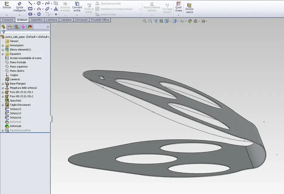
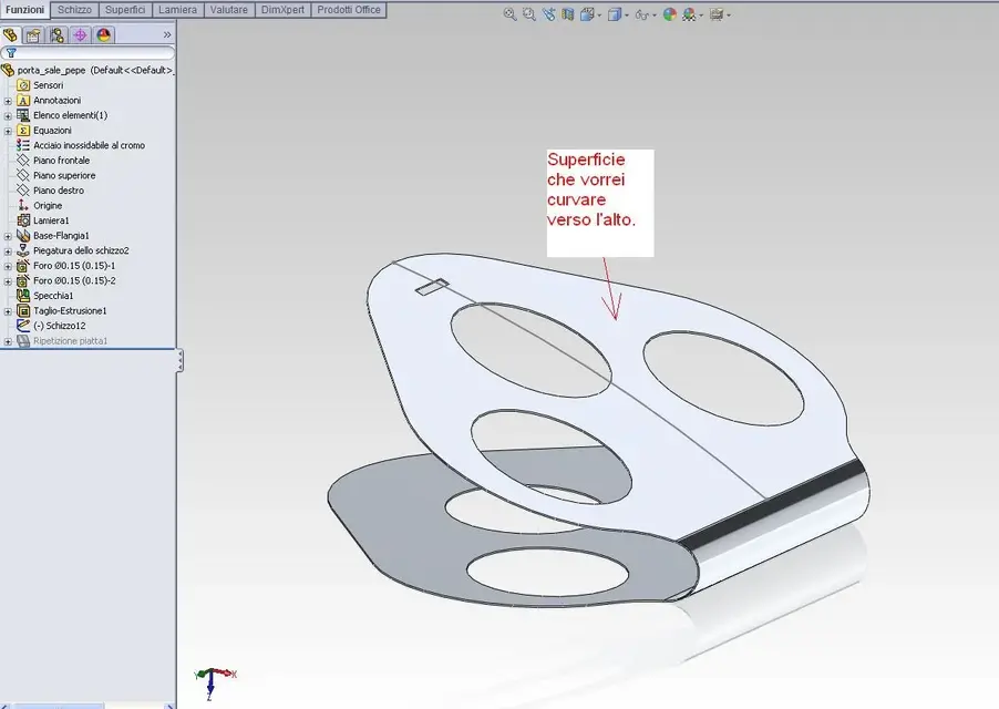
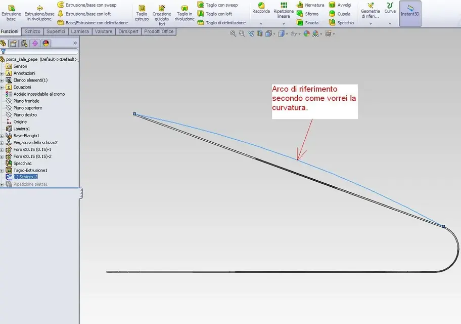
I would like to realize the curvature only of the inclined part of the object that is seen in the image, which is nothing but a portal and pepper (insoma is an exercise:biggrin:).

Therefore I would like to give a curve of the upper part, but that it was not "spherical" and that is, as if the entire surface was rested on a sphere, but that it curved the whole surface only in one direction.

In practice I would like the curvature to follow the circle arc that I designed as a track on the same plane of the same arc, that is, on what solidworks calls "upper floor" without affecting other directions.

basically a curve on one floor.

in the two images I posted maybe you understand better than how I explained it.:biggrin:

I then tried with the "deform" command, but I got everything except what I wanted to get. In particular I do not understand very well how to orient the terna of axes so that it takes all the surface and not only a piece of it. as an option of the "deform" command I chose "painted surface" but I don't know if it is the right one. However, the "point" option must be wrong for sure because it lifts me precisely, only a small area of the surface.

I followed the right method, or is there a simpler way to get this?

thank you all!:smile:

Light
 

Attachments

  • Superficie_curva.webp
    Superficie_curva.webp
    54.7 KB · Views: 50
  • Superficie_curva_2.webp
    Superficie_curva_2.webp
    59.4 KB · Views: 41
therefore does not lean on a sphere but on a cylinder (in one direction).

Then you could do as I did in the attached part, I did not shape as you did, it was just to make you cpaire as to leave.
 

Attachments

Hello, everyone!

as I said in the previous discussion "reflections glossy missing on model"
I would like to realize the curvature only of the inclined part of the object that is seen in the image, which is nothing but a portal and pepper (insoma is an exercise:biggrin:).

Therefore I would like to give a curve of the upper part, but that it was not "spherical" and that is, as if the entire surface was rested on a sphere, but that it curved the whole surface only in one direction.

In practice I would like the curvature to follow the circle arc that I designed as a track on the same plane of the same arc, that is, on what solidworks calls "upper floor" without affecting other directions.

basically a curve on one floor.

in the two images I posted maybe you understand better than how I explained it.:biggrin:

I then tried with the "deform" command, but I got everything except what I wanted to get. In particular I do not understand very well how to orient the terna of axes so that it takes all the surface and not only a piece of it. as an option of the "deform" command I chose "painted surface" but I don't know if it is the right one. However, the "point" option must be wrong for sure because it lifts me precisely, only a small area of the surface.

I followed the right method, or is there a simpler way to get this?

thank you all!:smile:

Light
Hi arz...


How it goes I wanted to do a caty test you could post an iges with your reference curve

Hi.

 
therefore does not lean on a sphere but on a cylinder (in one direction).

Then you could do as I did in the attached part, I did not shape as you did, it was just to make you cpaire as to leave.
Hello, King.

That's right! !
He understood right, it's like he leaned right on a cylinder!:finger:
If I had used this term to explain, I would have been clearer. However I see that you understood the same!:biggrin:

Basically it is like creating "an arch" of the upper part with convexity facing up.

Yes, in fact your method was better, because from the sketch from which you left, practically the curvature give it to you with an arch and the game is done.

But I'd like to know if I can do the same on my model without having to do it again and, dismantling a little with the functions of solidworks, I saw one that maybe could do to my case: the function "flettere".

Do you think it might serve for purpose?
As soon as I have a little time I try it and see, what do you say?

Thank you very much for the model!
You suggested me an approach that had not come to mind!:finger:
Hi arz...


How it goes I wanted to do a caty test you could post an iges with your reference curve

Hi.

Hello rs4!

Well, thank you, and you?
Is it as hot as you are?
here he also snaps by moving a finger.

Yes, I'm willing to place it.
so if you want, you can try to see how it comes with catia.

thanks also to you!:smile:
 

Attachments

Hello, King.

That's right! !
He understood right, it's like he leaned right on a cylinder!:finger:
If I had used this term to explain, I would have been clearer. Anyway, I see you got the same thing.

Basically it is like creating "an arch" of the upper part with convexity facing up.

Yes, in fact your method was better, because from the sketch from which you left, practically the curvature give it to you with an arch and the game is done.

But I'd like to know if I can do the same on my model without having to do it again and, dismantling a little with the functions of solidworks, I saw one that maybe could do to my case: the function "flettere".

Do you think it might serve for purpose?
As soon as I have a little time I try it and see, what do you say?

Thank you very much for the model!
You suggested an approach that I didn't think of!


Hello rs4!

Well, thank you, and you?
Is it as hot as you are?
here he also snaps by moving a finger.

Yes, I'm willing to place it.
so if you want, you can try to see how it comes with catia.

thanks also to you!:smile:
All right...... also here is so hot that pa....e:confused:

I'll coach you how I'll do it.

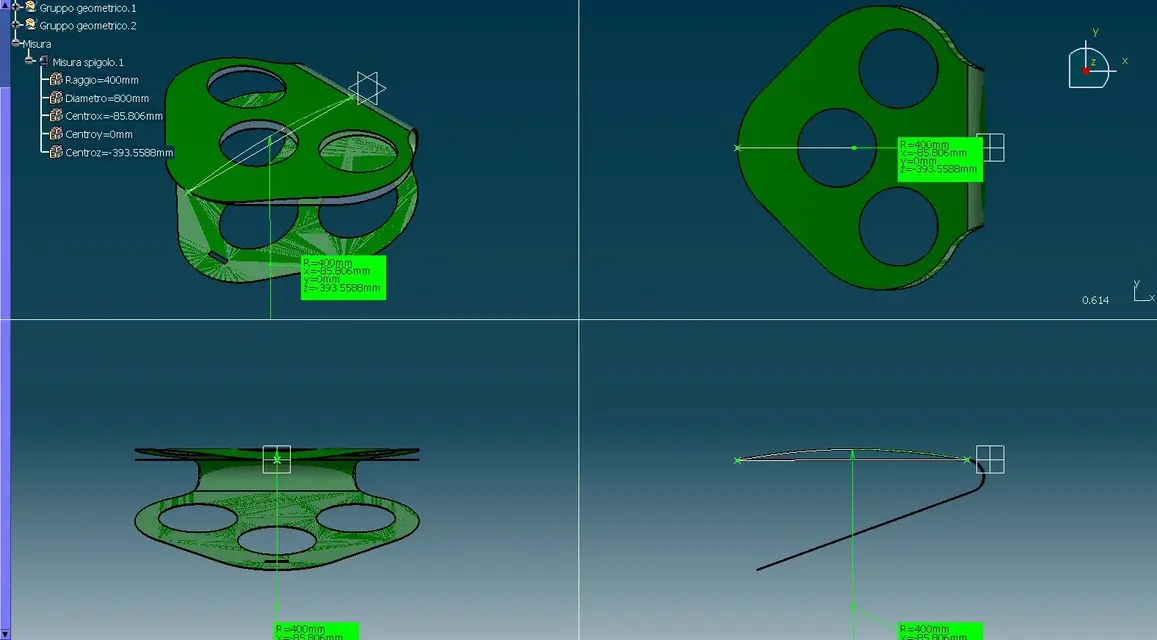
1 arc construction I used r400
2 upper surface with deformation coating on previously constructed arch
3 surface connection deformed with lower surface all in tangency
4 union
5 solidification

Hi.


Attachments

  • porta_sale_pepe_RS4.rar
    porta_sale_pepe_RS4.rar
    338.7 KB · Views: 11
  • porta_sale_pepe_RS4_superficie_su_curva_di_riferimento.webp
    porta_sale_pepe_RS4_superficie_su_curva_di_riferimento.webp
    85.4 KB · Views: 43
Hello, King.

That's right! !
He understood right, it's like he leaned right on a cylinder!:finger:
If I had used this term to explain, I would have been clearer. However I see that you understood the same!:biggrin:

Basically it is like creating "an arch" of the upper part with convexity facing up.

Yes, in fact your method was better, because from the sketch from which you left, practically the curvature give it to you with an arch and the game is done.

But I'd like to know if I can do the same on my model without having to do it again and, dismantling a little with the functions of solidworks, I saw one that maybe could do to my case: the function "flettere".

Do you think it might serve for purpose?
As soon as I have a little time I try it and see, what do you say?

Thank you very much for the model!
You suggested me an approach that had not come to mind!:finger:
proof with sketch bending between the controls of the sheet.
 
Hey, guys!

you were very kind both!:finger:

Unfortunately, however, I did not manage to bend the surface as I would have liked nor as rs4 did, whose result is exactly what I wanted to achieve.

rs4, you managed to create the arch just as I would like to do, only that in solidworks I don't know exactly how to do it to accomplish it while following your very just procedure.

re_solidworks, I tried with the command "pitching of sketch" as you suggested to me, but it doesn't seem to me that it goes well (I can always wrong but since I do not use solidworks for a long time) because, to what I understood, it realizes a fold, but of an entire flap around axis, while I would like to arch the surface to have a final result like that in your model, or like that obtained rs4 with a cas.

If you can do it with catia, I think that even with solidworks you can, only that until now I have failed.

You know how I could do that?

Thank you! :smile:
 
Hey, guys!

you were very kind both!:finger:

Unfortunately, however, I did not manage to bend the surface as I would have liked nor as rs4 did, whose result is exactly what I wanted to achieve.

rs4, you managed to create the arch just as I would like to do, only that in solidworks I don't know exactly how to do it to accomplish it while following your very just procedure.

re_solidworks, I tried with the command "pitching of sketch" as you suggested to me, but it doesn't seem to me that it goes well (I can always wrong but since I do not use solidworks for a long time) because, to what I understood, it realizes a fold, but of an entire flap around axis, while I would like to arch the surface to have a final result like that in your model, or like that obtained rs4 with a cas.

If you can do it with catia, I think that even with solidworks you can, only that until now I have failed.

You know how I could do that?

Thank you! :smile:
Guys, I did it! !

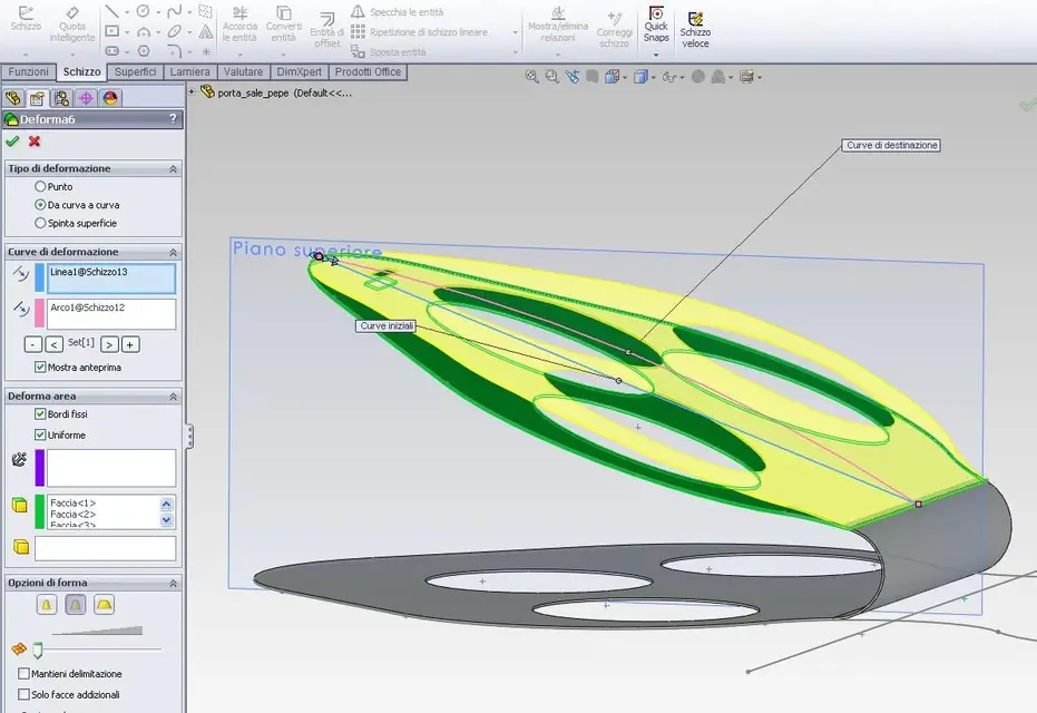
I used the "deform" function and the result is exactly what I wanted to get, as from attached image.

I used the "curve to curve" method I unchecked "delimitation retains" and in "other faces to deform" I selected the lower and upper face and also the faces between the two main surfaces (to say the truth I thought it was enough to select only the upper and lower face and then he automatically took account of the faces given by the thickness, but the result I got it).

I just wanted to know if you could do it in another way or if that's the only way.

thanks to both for the precious suggestions without which I would never make it!:finger:
 

Attachments

  • Superficie_curva_4.webp
    Superficie_curva_4.webp
    68.2 KB · Views: 21
  • Superficie_curva_3.webp
    Superficie_curva_3.webp
    83.2 KB · Views: 18
Guys, I did it! !

I used the "deform" function and the result is exactly what I wanted to get, as from attached image.

I used the "curve to curve" method I unchecked "delimitation retains" and in "other faces to deform" I selected the lower and upper face and also the faces between the two main surfaces (to say the truth I thought it was enough to select only the upper and lower face and then he automatically took account of the faces given by the thickness, but the result I got it).

I just wanted to know if you could do it in another way or if that's the only way.

thanks to both for the precious suggestions without which I would never make it!:finger:
a question: Do you have to get the development of that shape? I have doubts that it works with deformity.
 
a question: Do you have to get the development of that shape? I have doubts that it works with deformity.
in fact you are perfectly right, I sang victory too soon!:biggrin:

immediately after obtaining the result, I tried the function "flat repetition" and, as I wanted to prove, it did not work.

Yes, I would like to achieve development and with the deformed command is not as good as I had initially thought.

so the only way is to use the functions for the sheet and, in this regard, the only one I would have thought is the command "forming instrument".

Even if I've never used it, I've seen that it needs another element as a matrix, but I honestly have doubts that I can do in my case.

In short, but there will also be a way to curve a sheet in this way with a program like solidworks.:smile:

If I had to build it really, first I would make the fold in half of the piece with a semicircular punch with the same diameter of curvature of the central fold and, secondly, to realize the upper arch, I would always use a semicircular punch of diameter 400 by hypothesis (as did rs4) and so I would have realized the object (admitted and not allowed that I did not say some cabbage!).

If you had to realize the curvature on my model without starting again, (with solidworks you mean) do you have any idea how you could do it?

I'm sorry if I still break the boxes, but I'd like to make it with swx. On the other hand it doesn't seem very complex, but I can't do it.

Thanks again!:smile:
 
solidworks sheet, such as the module of all cads, facilitates the designer in finding development. What does that mean? you model the finished without worrying too much and then you get the development. that object can be modeled as I did, with a solid transformed into sheet metal at the end, with surfaces turned into sheet metal at the end.
all these modes require you to start again. Forming tools do not serve for this purpose, but serve to place small funnels, look in the guide and see well what you can do.
to shape that example I took less than 1 minute, so to do it finished as yours will take you to max 5 minutes.
I would start again with the correct approach.
 
If you had to realize the curvature on my model without starting again, (with solidworks you mean) do you have any idea how you could do it?
if you pay attention and use the sketch and quotas correctly with Sketch bending You can get there:Immagine.webp... and check the file: View attachment porta_sale_pepe SMPM.rar . the form there is and the development works.

otherwise the simplest solution that gives you more chance to have "various forms" would immediately make the sheet metal sketch with the folded/coated profile, obtaining of course a rectangular sheet that you will cut/work after the desired shape.

returning to the construction procedure you will first have to do the wide curvature at radius 400 and then the piego (r10) to close it on itself... not vice versa as you mentioned: how do you insert the r400 punch with the already folded sheet? (even without punches the first operation can be a displacement on the flap that curved r400, and then a half-mill in r10. of course "from the real" starts from the complete and finished shape of the laser cut sheet).

greetings
Mar
 
solidworks sheet, such as the module of all cads, facilitates the designer in finding development. What does that mean? you model the finished without worrying too much and then you get the development. that object can be modeled as I did, with a solid transformed into sheet metal at the end, with surfaces turned into sheet metal at the end.
all these modes require you to start again. Forming tools do not serve for this purpose, but serve to place small funnels, look in the guide and see well what you can do.
to shape that example I took less than 1 minute, so to do it finished as yours will take you to max 5 minutes.
I would start again with the correct approach.
Thank you, King, I share what you said, as soon as I have a little time, I try the solution that suggested me sampom, if then I still can't, start again, so much the piece is not difficult and I start again with a different approach as you say that maybe it is the best solution. Yeah, I figured it out by watching the help. The "forming" function is for funnels, for what I have to do, nothing has to do with it.

I'll let you know as soon as possible.

for the moment thank you so much!!

if you pay attention and use the sketch and quotas correctly with Sketch bending You can get there:View attachment 23035... and check the file: View attachment 23034 . the form there is and the development works.

otherwise the simplest solution that gives you more chance to have "various forms" would immediately make the sheet metal sketch with the folded/coated profile, obtaining of course a rectangular sheet that you will cut/work after the desired shape.

greetings
Mar
Hello, Marco!

you are perfectly right also, in fact tonight, just before falling asleep, I was clarified the correct use of the function "string" that I had not used correctly. In fact I think I understand how you use it and your explanation confirms it to me!:finger: (Also re_solidworks had suggested that I did not know how to interpret it. mea culpa!:biggrin:).
returning to the construction procedure you will first have to do the wide curvature at radius 400 and then the piego (r10) to close it on itself... not vice versa as you mentioned: how do you insert the r400 punch with the already folded sheet?
Yes, yes, I said a chestnut, I noticed immediately after I wrote it, only I didn't do it in time to correct!:tongue:

Thank you very much for the model! I can't wait to try the two streets, the one of kings (starting from head) and yours, but I think I can get there correctly using the "scratching". As soon as I can tell you.

Meanwhile thank you very much to both of you for your patience and I hope to return as soon as I impratichisco a little more with swx!:smile:

Bye.

Light
 
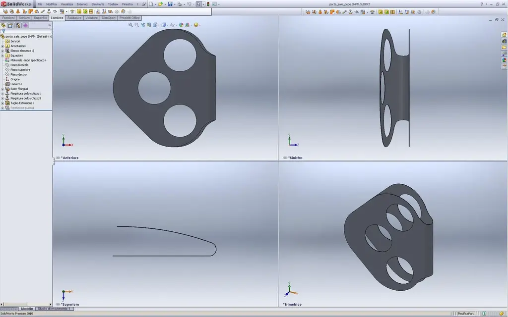
Perfect!! correctly using the "string" command I managed perfectly!

even the flat repetition comes perfectly!

before I couldn't because I didn't understand the operation of the command well. now, thanks to you, I understand.:finger:

in the image there is the final result.

In fact, looking at the help, I didn't realize very well how the command worked because the example he did refers to bending a flap at any 90° and I didn't think that varying degrees you could increase the width of the curvature until you reach the desired result.

I like it when with a 3d program I can do what I want without so much to turn around to satisfy the limitations of the software, well aware, of course, that sooner or later it will happen to hit us head and then the enthusiasm will fall a little, but on the other hand, it is right so.

I also want to try to experiment with another system to build the piece by starting from the top and then see which one is better to use.

for now, thanks again and next!:smile:

Bye.
Light
 

Attachments

  • portasale_curvo.webp
    portasale_curvo.webp
    59.9 KB · Views: 18
if you pay attention and use the sketch and quotas correctly with Sketch bending You can get there:View attachment 23035... and check the file: View attachment 23034 . the form there is and the development works.

otherwise the simplest solution that gives you more chance to have "various forms" would immediately make the sheet metal sketch with the folded/coated profile, obtaining of course a rectangular sheet that you will cut/work after the desired shape.

returning to the construction procedure you will first have to do the wide curvature at radius 400 and then the piego (r10) to close it on itself... not vice versa as you mentioned: how do you insert the r400 punch with the already folded sheet? (even without punches the first operation can be a displacement on the flap that curved r400, and then a half-mill in r10. of course "from the real" starts from the complete and finished shape of the laser cut sheet).

greetings
Mar
hi marco, a curiosity: how do you insert the link of the attachment (photo or other) at any point of the message? Is it a tool that only moderators have available or can other users do it?

Hi.

Thank you.

Light
 
hi marco, a curiosity: how do you insert the link of the attachment (photo or other) at any point of the message? Is it a tool that only moderators have available or can other users do it?
use the icon with the thumbnail, among the buttons found above the writing field.

greetings
Marco:smile:
 
hi marco, a curiosity: how do you insert the link of the attachment (photo or other) at any point of the message? Is it a tool that only moderators have available or can other users do it?

Hi.

Thank you.

Light
Bye-bye guys

I tried with the sheet metal too.

Let's see what you think and maybe compare the methods.

and more appropriate to do before or after the cut out??? I did before to see if it bended equal!

1 surface thickness of 0.5 mm without cut out
2 solid recognition in sheet metal
3 creation cut out
4 scourge of r 400 iml on the floor with fixed point


allego img and iges of the file produced by catia v5

greetings


Attachments

  • porta_sale_pepe_RS4_2_img_1.webp
    porta_sale_pepe_RS4_2_img_1.webp
    93.6 KB · Views: 9
  • porta_sale_pepe_RS4_2_img_2.webp
    porta_sale_pepe_RS4_2_img_2.webp
    43.3 KB · Views: 9
  • porta_sale_pepe_RS4_2.rar
    porta_sale_pepe_RS4_2.rar
    189 KB · Views: 3
Bye-bye guys

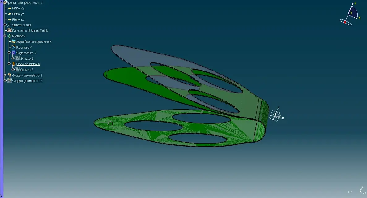
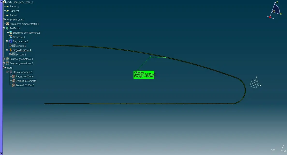
I tried with the sheet metal too.

Let's see what you think and maybe compare the methods.

and more appropriate to do before or after the cut out??? I did before to see if it bended equal!

1 surface thickness of 0.5 mm without cut out
2 solid recognition in sheet metal
3 creation cut out
4 scourge of r 400 iml on the floor with fixed point


allego img and iges of the file produced by catia v5

greetings

Hello rs4!

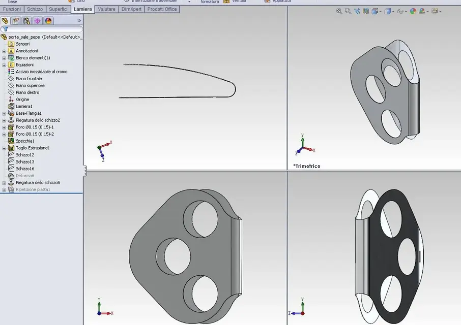
for me your procedure is great, I too have done as you and that is: first I created the sketch with the shape of the portal, then I gave it the thickness of 0.5 mm as sheet, then I created the holes (always with the figure in the plane) for the containers of the salt and pepper, then I created the central fold of radius 10 with the command "pitching" and last I curved the surface with radius 400 with the same command (probably the command is analogous to your "foot").

Yes, in my opinion it is better to make the cut out as you did, so you can see if they also bend together to the surface.

Thanks for trying too, it is another confirmation that I also followed a logical procedure.:smile:

Bye.

Light
 
Hello rs4!

for me your procedure is great, I too have done as you and that is: first I created the sketch with the shape of the portal, then I gave it the thickness of 0.5 mm as sheet, then I created the holes (always with the figure in the plane) for the containers of the salt and pepper, then I created the central fold of radius 10 with the command "pitching" and last I curved the surface with radius 400 with the same command (probably the command is analogous to your "foot").

Yes, in my opinion it is better to make the cut out as you did, so you can see if they also bend together to the surface.

Thanks for trying too, it is another confirmation that I also followed a logical procedure.:smile:

Bye.

Light
not to break the boxes, but according to me the round cuts for the containers of salt and pepper were made last. If you do them first and then pierce them the jar no longer enters with uniform play.
 
Hello rs4!

for me your procedure is great, I too have done as you and that is: first I created the sketch with the shape of the portal, then I gave it the thickness of 0.5 mm as sheet, then I created the holes (always with the figure in the plane) for the containers of the salt and pepper, then I created the central fold of radius 10 with the command "pitching" and last I curved the surface with radius 400 with the same command (probably the command is analogous to your "foot").

Yes, in my opinion it is better to make the cut out as you did, so you can see if they also bend together to the surface.

Thanks for trying too, it is another confirmation that I also followed a logical procedure.:smile:

Bye.

Light
hi arzi thanks you more or less are those the landscapes

How come you made two folds one by 10 in which area??? and a 400???, in a single blow you couldn't???, or for your personal need? ? ?
not to break the boxes, but according to me the round cuts for the containers of salt and pepper were made last. If you do them first and then pierce them the jar no longer enters with uniform play.
Hello, King.

If we talk about physical technical reproducibility even in my opinion they must be done after bending because if you do them before they ovalize...., then it must be folded into the appropriate mold tool engaged with pins and rifilato.

this for me is the right procedure
and more appropriate to do before or after the cut out??? I did before to see if it bended equal!How can you read I made them first just to see if it folded the same I mistakenly wrote the catia in the previous message


Hi.

thanks rs4
 

Forum statistics

Threads
44,997
Messages
339,767
Members
4
Latest member
ibt

Members online

No members online now.
Back
Top