KRLE
Guest
Hello
after various searches around I thought I would ask this question to you hoping to find someone who has some experience regarding
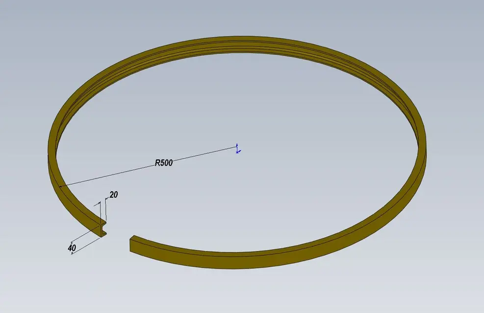
displacement of profiles to u. ( 25x12sp4 - 30x15sp4.5 -35x17sp5.5 – 40x20sp6).
having more and more often need to respect diameters imposed by the application, I found myself several times not to adjust exact profile development using solidworks.
precise that solidworks I use since 98 and so far I have solved all the problems but this time
I couldn't find a valid "k factor" to bend the profiles while for the diameters up to 2000mm I can stand it (doctor k 0.43), the most serious thing and that increasing of error diameter between sw and carpenter becomes + big and then I am forced to trust him, or make the displacement and then make adjustments to the work cutting or adding of the profile.
I know for certain that these applications are very used in the agricultural sector (dryers – silos ..). and surely the system to calculate developments of the profiles there.
or I would like to know if there are any software that does it perfectly.
I'll attach you some photos to make you know what I'm talking about.
I appreciate your advice
Thank you very much.
after various searches around I thought I would ask this question to you hoping to find someone who has some experience regarding
displacement of profiles to u. ( 25x12sp4 - 30x15sp4.5 -35x17sp5.5 – 40x20sp6).
having more and more often need to respect diameters imposed by the application, I found myself several times not to adjust exact profile development using solidworks.
precise that solidworks I use since 98 and so far I have solved all the problems but this time
I couldn't find a valid "k factor" to bend the profiles while for the diameters up to 2000mm I can stand it (doctor k 0.43), the most serious thing and that increasing of error diameter between sw and carpenter becomes + big and then I am forced to trust him, or make the displacement and then make adjustments to the work cutting or adding of the profile.
I know for certain that these applications are very used in the agricultural sector (dryers – silos ..). and surely the system to calculate developments of the profiles there.
or I would like to know if there are any software that does it perfectly.
I'll attach you some photos to make you know what I'm talking about.
I appreciate your advice
Thank you very much.

")