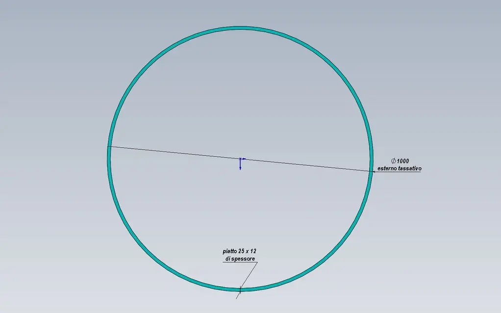
• This forum is the machine-generated translation of www.cad3d.it/forum1 - the Italian design community. Several terms are not translated correctly.

development of u -calandrati profiles

  • Thread starter Thread starter KRLE
  • Start date Start date
Status
Not open for further replies.
This is a hot profile, what does the bending factor have to do?
:confused:
I believe it refers to the development of the u 40x20. (the profile at u considers it sheet).
:confused::confused:

I get less and less...
The problem in such a profile is to understand where the black fiber is, or where the pigs can place it. It's different, by the way, if you fold it from above, below or side.

Where does this empirical rule come from, just to understand together?
 
:confused:

:confused::confused:

I get less and less...
The problem in such a profile is to understand where the black fiber is, or where the pigs can place it. It's different, by the way, if you fold it from above, below or side.

Where does this empirical rule come from, just to understand together?
thanks for having specified the question
Things are exactly like that. thanks to practical evidence, we realized that turning with the face on one side or other development changes.
However, I am convinced that producers of coffee have such software
 
x pomp

because the development I calculated as you say (and then I had to cut extra stuff) that I am now looking for a right formula

However if things were like that then you tell me how to turn flats with 8mm thickness up???
for you then 8614mm e 8582mmAre these things?
 
cmq calculation is simple = 40+20+20-6-6-6-6+factor fold (2)=58
2742x3.14+factor fold=8584
That's the wrong calculation. should give 2742x3.14+58=8667
x pomp

because the development I calculated as you say (and then I had to cut extra stuff) that I am now looking for a right formula

However if things were like that then you tell me how to turn flats with 8mm thickness up???
for you then 8614mm e 8582mmAre these things?
questi of the Scottish dove?
krle tell me what the primitive diameter with development is about?
the primitive should be the theoretical one derived from the calculation.

I think we're getting a little square with the calculations.
 
x pomp

you give me exact development for that and then I'll tell you what it's about?
 

Attachments

  • piatto 25x12.webp
    piatto 25x12.webp
    30.9 KB · Views: 23
When I worked at the counter, I was adjusting like this:

I calculated the development in axle to the thickness (ø wanted+1 time the thickness * 3.14), then I cut the profile 20/25 cm longer because the first part is unable to reach.
I tracked, straight bar, with the tip sign this development (ø wanted+1 time the thickness * 3.14) on the bar and used the signs as a reference to make the ring coincide.
once the first fell, I cut the excess pieces by checking that the signs matched, if not dragged a snitch so that the ø wanted was correct.
this modification I annotated so that the next pieces I cut them already more
long of the only exact discard that I would have removed after the roller.
I fixed with clamp, or faster with a nice welding point, and I cut the "molla" obtained by making it a ring.
from the image perhaps you understand better.

Hi.
 

Attachments

  • Anello caladrato.webp
    Anello caladrato.webp
    52.1 KB · Views: 11
... so I cut the profile 20/25 cm longer because the first part is unable to reach. . .
That's right. what sense does it make to use a fantomatic program to calculate the precise development if then you should still cut off the head and tail? is it not at this point that we adjust with the quantity to be trimmed? If I'm saying a cow, tell me.
@ klre: what tolerance do you need?
 
When I worked at the counter, I was adjusting like this:

I calculated the development in axle to the thickness (ø wanted+1 time the thickness * 3.14), then I cut the profile 20/25 cm longer because the first part is unable to reach.
I tracked, straight bar, with the tip sign this development (ø wanted+1 time the thickness * 3.14) on the bar and used the signs as a reference to make the ring coincide.
once the first fell, I cut the excess pieces by checking that the signs matched, if not dragged a snitch so that the ø wanted was correct.
this modification I annotated so that the next pieces I cut them already more
long of the only exact discard that I would have removed after the roller.
I fixed with clamp, or faster with a nice welding point, and I cut the "molla" obtained by making it a ring.
from the image perhaps you understand better.

Hi.
That's how you do it, because in the head and tail are straight.
then put it on the ground and cut the terminals.
 
Last edited by a moderator:
tolerance + - 5mm in diamerto

However the thing that escapes you and the big diameter for which you do not need to cut the head and the tail (then I can bend everything) and the important thing???? ? holder does not want to cut (Add) nada
 
It will be...but I, rather than finding myself a software that makes 'ste robe, I would buy myself a flexible and a pack of cutting disks.
 
It will be...but I, rather than finding myself a software that makes 'ste robe, I would buy myself a flexible and a pack of cutting disks.
I agree with you:finger:, but I can assure you that in front of our constant increase of work (and gain):biggrin: sometimes it is no longer worth making these arguments.
the maximum optimization of production
 
tolerance + - 5mm in diamerto

However the thing that escapes you and the big diameter for which you do not need to cut the head and the tail (then I can bend everything) and the important thing???? ? holder does not want to cut (Add) nada
then you have to run a sample with your theoretical measures that you will correct by putting in "quadro" the piece use the possible error to correct
exact development.
each type of profile has a different withdrawal/length, so the best way is to try with a piece.
to the maximum the blacksmith will have to arrange only one piece, if if if it stretches it must only make an extra welding.
By the way, can you find the bars above 6 meters? (see your development).
 
x mike
no bars are soldered between them to measure and then curved

However – after practical tests the theoretical measurement for the profile 40x20
would be like to turn the plate 12mm thick
 
x mike
no bars are soldered between them to measure and then curved

However – after practical tests the theoretical measurement for the profile 40x20
would be like to turn the plate 12mm thick
well, as you see all the theory that we can study of infranges against
the reality of the metal, then consider that these profiles have, already in production, the tolerances that can send to hoof all possible and imaginable calculations.
by curiosity, do you land them horizontally (axis vertical rollers) ?
 
would there be another small detail, and the material variable?
If the hardware belongs to two different castings I think you don't get the same developments.
a tolerance +/5 mm on the diameter means that you have about 1.8% as error margin.
Happy birthday.
I think your boss needs a cure.
 
would there be another small detail, and the material variable?
If the hardware belongs to two different castings I think you don't get the same developments.
a tolerance +/5 mm on the diameter means that you have about 1.8% as error margin.
Happy birthday.
I think your boss needs a cure.
very true, where I work I bend altoresstential sheets with thicknesses from 3 to 12mm (sometimes 15mm), after a bit of tests and measurements we saw that different thicknesses require different k factors, different bend angles require different k factors, different materials require different k factors, "naturally" steels with equal characteristics of different manufacturers behave differently (maybe only for folds over 20°-30°).
Finally the same sheet of the same manufacturer, obtained from different castings can give different results under the bending machine.
to return to the subject profile of the discussion, I believe that the only way to find the neutral ray is to obtain it from auditions (2 or 3 at least), and this is easy; then it is necessary to hypothesize a maximum +/- variation of the neutral radius, and this is more difficult if you do not make sufficient samples (using profiles of different origin) for a statistical analysis; This should be assessed if the tolerances necessary for the finished piece are to be agreed with the actual size that can take the artifact, otherwise it will be necessary to stay at the top end of the tolerance and to trim when necessary.

but what is the month of the tilted leaders?
 
very true, where I work I bend altoresstential sheets with thicknesses from 3 to 12mm (sometimes 15mm), after a bit of tests and measurements we saw that different thicknesses require different k factors, different bend angles require different k factors, different materials require different k factors, "naturally" steels with equal characteristics of different manufacturers behave differently (maybe only for folds over 20°-30°).
finally the same sheet of the same manufacturer, obtained from different castings can give different results under the bending machine... .
... add the direction of lamination, the type of machine used, knives and matrices... etc. etc.
at the end for "precise" jobs every workshop has its parameters that the designer then inserts into the cad.

:smile:
 
very true, where I work I bend altoresstential sheets with thicknesses from 3 to 12mm (sometimes 15mm), after a bit of tests and measurements we saw that different thicknesses require different k factors, different bend angles require different k factors, different materials require different k factors, "naturally" steels with equal characteristics of different manufacturers behave differently (maybe only for folds over 20°-30°).
Finally the same sheet of the same manufacturer, obtained from different castings can give different results under the bending machine.
to return to the subject profile of the discussion, I believe that the only way to find the neutral ray is to obtain it from auditions (2 or 3 at least), and this is easy; then it is necessary to hypothesize a maximum +/- variation of the neutral radius, and this is more difficult if you do not make sufficient samples (using profiles of different origin) for a statistical analysis; This should be assessed if the tolerances necessary for the finished piece are to be agreed with the actual size that can take the artifact, otherwise it will be necessary to stay at the top end of the tolerance and to trim when necessary.

but what is the month of the tilted leaders?
all because of the increase of the iva.... :biggrin:
... add the direction of lamination, the type of machine used, knives and matrices... etc. etc.
at the end for "precise" jobs every workshop has its parameters that the designer then inserts into the cad.

:smile:
quoto, for years I have established retreats and extensions and with ns equipment
we work in the order of tenths of mm with thickness up to 8 mm.
 
Status
Not open for further replies.

Forum statistics

Threads
44,997
Messages
339,767
Members
4
Latest member
ibt

Members online

No members online now.
Back
Top