• This forum is the machine-generated translation of www.cad3d.it/forum1 - the Italian design community. Several terms are not translated correctly.

sweep solida sw11

  • Thread starter Thread starter grace46
  • Start date Start date

grace46

Guest
Good evening, everyone.
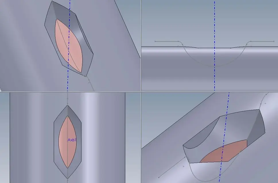
having to simulate a path of candle milling (a 90° sharp hole) while performing a circular interpolation according to the z axis (in vertically penetrating gradually to the maximum depth, in the center of the circle arc, then symmetrical to the starting point), I used the solid sweep function.
I designed the tool as a rotation solid.
I designed the circle arch as a profile to be covered.
I designed a vertical axis as an intersection of the right and frontal planes.
when generating the solid sweep with the tool in the blue field, the trajectory in the pink field, follow the profile with vector (inserting the vertical axis in the field), the excavation is correct.
if, however, I exceed the depth of the conical part of the tip so that the cutting edge is constituted by the straight inclined to 45° and the vertical stem, the result is abnormal.
I'd like help.
attach a zip containing 2 rows: one with tool tip angle of 60° (which works only on the tilted cutting edge), the other with angle at 90° (which works on the tilted side and on the vertical one).
Thank you.
 

Attachments

It's perfect!
If you don't mind giving me an explanation.
I don't think it's just because I moved the profile application point.
Instructions speak that both on or within the tool profile.
Thank you for answering me.
 
It's perfect!
If you don't mind giving me an explanation.
I don't think it's just because I moved the profile application point.
Instructions speak that both on or within the tool profile.
Thank you for answering me.
... uhmmm... Look at him, it doesn't look like you asked me.
apart from the amplitude of the path that is greater, but then is the "normal" of the tool that rotates following it; what kind of movement do you have to do? is always vertical and in that position "floating" following that arch? because in the solution placed the result is not that, look at the preview of the function that you understand what I mean.

greetings
Marco:smile:
 
I reviewed your processing more carefully.
is not the result of the tool's work (even if the profile is correct) as you rotate it around the profile center, while in a working center the tool is always (in this case) perpendicular to the surface to work.
if you notice well you have 2 lines on the profile due to the tool cylinder.
In reality you should have only one edge (the connecting cylinder and cone).
I tried to put the verticality condition with vector the axis but the result is not yet accurate.
 
I was writing while you were making your right remarks.
the mill must remain vertical.
Thank you.
 
thanks to both for the right criticism.
I did other tests, trying to respect the correct size of the arc and trying to put as a vector of direction one of the flat faces of the pipe.
unfortunately the result and always staggered. I don't understand why.
 
ok for the result, I also solved it for points, but I was interested to understand well how the solid sweep works.
for the sweep profile there are no problems.
hello and thanks for the participation.
cesing
p.s.: I hope the "guru" of sw come forward.. .
 
Good evening, everyone.
having to simulate a path of candle milling (a 90° sharp hole) while performing a circular interpolation according to the z axis (in vertically penetrating gradually to the maximum depth, in the center of the circle arc, then symmetrical to the starting point), I used the solid sweep function.
(cut)
if, however, I exceed the depth of the conical part of the tip so that the cutting edge is constituted by the straight inclined to 45° and the vertical stem, the result is abnormal.
I'd like help.
if you take the path with a straight stroke connected to the arc with a fitting works.
eye that if you try to change the rope of the arc and exceed certain values then the function fails. probably there are problems of intersection between the volume of the tool and the path that the program fails to solve.
as for the solid sweeps (or dug) when you use a section too large and turn it with too sharp angles. :confused::frown: and it is a great break.. .
 

Attachments

Wow, marcof!
I didn't doubt the "guru" possibilities.
There are no precise rules on how to deal with the problem according to the different circumstances.
I put it together with tangence problems where you have to disconnect at least 0.01 mm!
Thank you and the next couple.
cesing
 
There are no precise rules on how to deal with the problem according to the different circumstances.
I put it together with tangence problems where you have to disconnect at least 0.01 mm!
Thank you and the next couple.
cesing
to understand the rules that are under us (because written clearly you don't find them...) you often have to use that certain function and by force of squash you learn.
In the example posted I thought that the starting point directly on the surface of the cylinder did not like it, then I moved out of the surface the starting point, but nisba. trying to connect it with a straight segment and a fitting worked.
Sometimes to find the solution takes a little fancy and a little ass in equal parts... :smile:
even having so much time to lose helps a lot:smile:
 
if you take the path with a straight stroke connected to the arc with a fitting works....
... true.
but you also made "the mistake" (perdonate the bold:biggrin:) to make "bascular" the cutting tool. you have to give him a direction vector that can be the axis put by grace46 or simply the upper plane, so that the mill always remains perpendicular along the path.
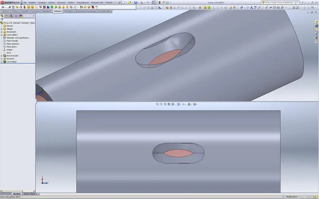
even so it works but you have to further change the sketch making the path "more sweet" (maybe, I think.. ste functions are a mystery. remembers and is definitely cousin of the helical sweep cut:tongue:):Prova a 45 smpm.webp
View attachment Prova a 45 smpm.rarthe footprint is different (without "points") and I cannot be sure that it is correct. definitely the resulting surface is not beautiful/perfect in aa++ class:biggrin:

greetings
Mar
 
... true.
but you also made "the mistake" (perdonate the bold:biggrin:) to make "bascular" the cutting tool. you have to give him a direction vector
There is little to quote... I really did a marone, nothing else!
I did not look at the preview of the default cut that is not with the direction vector
even so it works but you have to further change the sketch making the path "more sweet" (maybe, I think.. ste functions are a mystery. remember and is definitely cousin of the helical sweep cut:tongue:)
no for charity, do not evoke "the thing"... :smile:
however they are functions that go correctly up to certain limits, all to discover. . .
the footprint is different (without "points") and I cannot be sure that it is correct. definitely the resulting surface is not beautiful/perfect in aa++ class
apart from the question of aaaa is logical that the imprint is curved. If you make a small set and ties a cut of the same size to the path, converted into optimized spline, I think it follows. but you go ahead, that I'm laughing... :smile:
 
Thank you for your help.
You're just great.
I wonder if it is correct that a 3d (developed to treat geometry in space and also for mechanical use therefore of aid for design) go on a boat on a completely simple problem.
Is the cam the solution?
good weekend of week at all
cesing
 
I wonder if it is correct that a 3d (developed to treat geometry in space and also for mechanical use therefore of aid for design) go on a boat on a completely simple problem.
I don't think the geometry created by the sliding of a solid inside another is just trivial to solve. Besides, apart from the cams that seem to me create a "scaled" geometry according to the depth of the pass, I do not know which other cads can solve it creating an exact mathematical surface.
first I mentioned "the thing" referring to the helical excavation in a cylinder of a 2d profile that simulates the processing obtained with a candle mill.
do a search on the forum for "helicoidal waste" and light of the beautiful ones. :rolleyes:
 
I thank you for your valuable advice and extensive delucidations.
the profile generated by the processing of "sampom" seems to me the correct one because the diameter of 10 mm of the cylindrical cutting edge affects the profile already cut from the tip of the conical cusp. I don't want "marcof"!
It is probable that even a small complication of the shape of the tool puts in crisis the system of calculation of the profiles, as demonstrated by the fact that when the excavation is generated by a single inclination (my profile with angle 30°) there are no problems on the management of the resulting.
thank you again and I hope to reread you in other discussions, I repeat, you know in packages! !
Good Sunday
cesing
 
thank you again and I hope to reread you in other discussions, I repeat, you know in packages! !
Good Sunday
cesing
and this is the poor section of the forum (for software limitations).
On the other hand things happen that you humans... :biggrin:
 

Forum statistics

Threads
44,997
Messages
339,767
Members
4
Latest member
ibt

Members online

No members online now.
Back
Top