• This forum is the machine-generated translation of www.cad3d.it/forum1 - the Italian design community. Several terms are not translated correctly.

how would you do that? rolling blade...

  • Thread starter Thread starter simone03031986
  • Start date Start date
I am following the first procedure you indicated to me: I extruded the profile of the folded clip (the side view to understand us), after which I flattened it and cut to give it the form I wanted. But when I fill it back to the shape before the cut... where am I wrong?
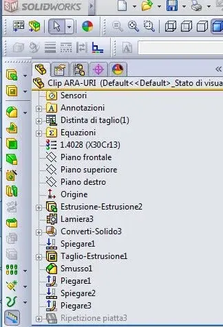
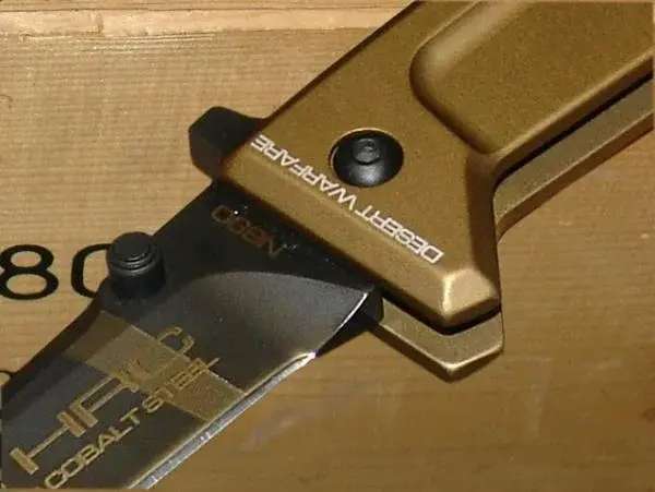
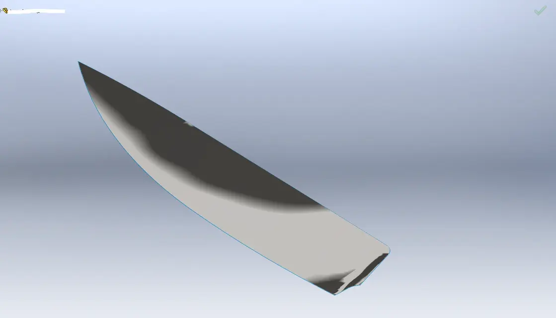
Sorry, my fault, I thought you knew that there is the function "distendi" and "piega" with which you stretch the sheet, cut and finally "pieghi" with the other function. . .
 

Attachments

  • dis.webp
    dis.webp
    5.9 KB · Views: 20
Thank you very much, if I looked a little more in the nose maybe I found it:smile:
 

Attachments

  • Clip03.webp
    Clip03.webp
    10.7 KB · Views: 12
always with regard to my clip created with "lamiera", is it possible that you can not collect the edges?
 
I attach the file.
I can't understand why...
... why it is articulated... I'm not here to explain why I'm not practical with these functions, let's say I never use them but when I need them I can get out pretty well... certain a modeler with the countercaxxi (not me) would solve by modeling the fitting with variable odds and how much more...
Look at the odds I set. . .

I have an intimate question... .
but what are the features folds and stretches that you have inserted after those spins??? (* I actually imagine :biggrin:). .

ok, now you just have to put on the table, quote and pull out the development* (here comes the asterisk :rolleyes:) for laser or mold...

*a beer we're having at that moment... :smile:
 

Attachments

Hi.
I have been involved in the design and production of sports coltelleria articles and recently I am a sw user.
I wanted to ask which, according to you, is the best method to model the rounding and thread of a blade (and perhaps even the dorsal or counterfeit).
by means of roasting means that processing by removal of material that "finances" the blade up to the thread of the same.
I attach an example image and a file of mine, in which, however, you can see a slip on the surface of the round.. .
Thank you, simone
the advice I give you is to work the 3d simulating the real work of the piece.
do not use your procedure with the surfaces.

for sheet metal speech in the last post, you have to understand that the sw sheet module covers the die-packing process, not molding.
so if your purpose is to find the flattened shape even if only indicative, I recommend you to model the piece normally and then convert it into sheet metal using the command of 'put folds'.
 
maniago, the city of knives...:-)

I'm interested in the modeling of the biscuits. But I'm curious about your question, can you explain better?

@marcof
You're right, I used a surface to remove the material.
I did so:
-extrusion of the upper half of the blade
-creation of all the various guidelines for the various profiles of the rounding-cutting
- surface with delimitation with sketches made above
-cut with surface
- mirror of half the blade

what you mean by "I think you have used quanche procedure with surfaces but with little control over the development of the same. "

I like your idea of the v cut, but then how do I manage the "agreement" at the beginning of the sharpening, since it is not really a fitting? I entered an image

ps: the discussion on the forging of the damask is really fantastic and very interesting, since I also use it. with sw I could study new methods and sequences between twists and folds of the package to create new plots. Thank you.
look, to the eye (it's a bit of time that not mastic sw since I now use proe, so it can be that I'm wrong) the modeling of your roasting is constituted in substance by two sections characteristics (at maximum three) and a guide curve; I think a loft cut is what you need.. .
 
@mike1967
I can't understand what you mean by "look at the odds I set...", however I managed to get the same result by selecting the pit faces that edges.
In fact there are a feature fold and spread more, perhaps in the sewage of the operations has escaped something.. .
In fact now there would be development to create the piece: laser cutting and bending. but for now I put it aside since the article is old and all these things are already there...however the beer proposal remains valid:biggrin:
ps: thanks for the file!

@soliduser
I have always tried to reason what the real steps can be to get my designs since I used rhino. I have always had some difficulty in shaping the blades, but finding a lamp of light with the bounded surfaces. But I am open to any kind of advice and I would be grateful if you had a custom made one for me.
on the sheet bending speech you are right, it makes no sense to reason with the fittings: In fact, to have the flat development of the clip, I have to suspend those features...it was right to have both the correct development (lamiera) and an aesthetic factor suitable for renderings.

@counterblow hammer
cutting with loft is the alternative I use (or better, I used) if the delimited surface does not work, but rarely gave me better results. . .

ps: who knows if and how do decals appear in modalities "removal hidden lines"?

Thank you, simone
 
Hi.
I have in my hands several knive projects that I would like to perform in the best way.
the problem remains the optimal modeling of the roasting and sharpening of my blades. I just can't find an optimal procedure especially for renderings: In fact, when I look at the modeling with the options "strisce zebra" or "curvatura" on, the imperfections are clearly noted.
If you want, for those interested in taking a look at it, I attach 2 files: in the first I create the roasting from nothing and then "add material" while in the second I perform cuts with the surfaces.
Thank you:
 

Attachments

in reality the rounding is made with the equivalent with a sweep excavation.

Of course if it was a mushroom knife.. .
 
Sorry the idiot question: but the final goal you're looking for? . . .

you say "optimal modelling of sharpening", but honestly I miss myself on the optimal signifcato. what then? ...
 
My problem is simple: I can't shape the blade's rounding well (and the wire), which you touch on me at the time of rendering.
 
Sorry the idiot question: but the final goal you're looking for? . . .

you say "optimal modelling of sharpening", but honestly I miss myself on the optimal signifcato. what then? ...
my problem is to be able to shape well that material removal work that in the world of cholera is called "arrotraction". It is that processing that progressively "sends" the thickness of the blade until it reaches the part that is then sharpened, the "filo".
especially I can't well collect the cutting surface in the "out" area as you see well in the image (my rendering) of 5 post back.
I attach an image to better explain what the roasting is.
 

Attachments

  • a2_4.webp
    a2_4.webp
    29.8 KB · Views: 24
Sorry the idiot question: but the final goal you're looking for? . . .

you say "optimal modelling of sharpening", but honestly I miss myself on the optimal signifcato. what then? ...
my problem is to be able to shape well that material removal work that in the world of cholera is called "arrotraction". It is that processing that progressively "sends" the thickness of the blade until it reaches the part that is then sharpened, the "filo".
especially I can't well collect the cutting surface in the "out" area as you see well in the image (my rendering) of 5 post back.
I attach an image to better explain what the roasting is.
I think the question of counterblow hammer is different. It's clear to everyone what you want to do, what you don't understand is why you want to do it. and from this why the modeling technique will come out.

technical design is not a representation of reality, but a series of information for the realization of a piece. modeling "good" something that is not then put on the table because it is not necessary, is, for the purposes of technical design, a useless effort.
so if your purpose is to make a constructive, you will have to draw only the edge of the roasting. If your purpose is to make a render, then things change. we are not talking about technical design, but of representative image. here the aesthetic value has its own because.

do not confuse you with the mental pippe that you make those that model car bodies, which have to turn the curves to perfection, looking and covering the model with zebra and trying to eliminate even the smallest "catcher". These pippe have their own because. that model is then used for milling cnc of a mold from which the sheet metal comes out. If you have a bruise on the surface, you will have the same bruise on the body shop maybe of a porsche, and then you will have a series of unpaid bills.

the process of making a knife is different. pin the blade on a grinding machine (I believe), you only want to know the angle and thickness, so a modelling technical of detail of the surface is perfectly useless.

I don't know if I explained.
 
...... If your purpose is to make a render, then things change. we are not talking about technical design, but of representative image. here the aesthetic value has its own because.
...... turn the curves to perfection, looking and looking at the model with zebra and trying to eliminate even the smallest "catching". These pippe have their own because. that model then is used for milling cnc of a mold.............
.
this is exactly what I want: to have a perfect 3d model to make excellent renderings, perfect visualizations in " zebra mode" and....because not even molds.
I apologize if, by mistake, I have spoken of technical drawing or table setting.. .
Thank you, simone
 
this is exactly what I want: to have a perfect 3d model to make excellent renderings, perfect visualizations in " zebra mode" and....because not even molds.
I apologize if, by mistake, I have spoken of technical drawing or table setting.. .
Thank you, simone
by means of moulds I would go with calm: for example in the field of forging, at least by personal experience, already a control of the curvature of the plumes is something "extreme"; I have seen that by imposing the objective of creating fittings that are functional to the process, but at the same time they are realized with the least possible "weaks" (and therefore in this case tightened control of the tangences) then, at the realization level, to a smoothness of the extremely respectable fittings.
do a control in "zebra" to make a mold makes sense only and exclusively if the piece from which you start to model the mold was designed with control in "zebra", otherwise you vien to cost the wrath of God!


As for the most realistic modelling possible of the sharpening at this point I don't have to advise you to take one of the sharpest knives you have, cut it perpendicularly to the thread and from there do the relief of what jumps out; from here we work with mixed modelling (superfici-solid) using all the tools for tangency and curvature controls and compare the result created with the real one. at this point you do your "zebra" checks for rendering and if you see that the result does not for you re-inizi from head changing the modeling so that it conforms simultaneously to the reality of the thread and to the requirements of rendering. to the eye that it is not said that you can get along with one or two iterations! I know that on the basis of what you want to get there will be to bang the marons well (maybe clashing even with some limit of the program... !

another thing I feel to recommend is never to lose contact with reality: Sometimes some "extreme" models only make nothing more than the "human" ones, but they cost you much more as time to realize them was excessive. And if your boss finds out... They're tears for your butt!
 
In the meantime I have found a possible solution that, at least for this particular one, satisfies me a lot.
In practice I created, with a lot of sketches but fast to do, the "width" of the surface that I will use to cut the solid of the "grick".
the function, of course, is called -filling the surface-: in the field "limit patches" we go the sketches that delimite the perimeter, while in "wine curves" we go the internal sketches.
I attach some images, just to share with you this thing that I hope may serve to someone else.
I just have to try this method on other details and see if it works....if you have any advice .....:smile:
 

Attachments

  • Immagine.webp
    Immagine.webp
    18.5 KB · Views: 14
  • Immagine2.webp
    Immagine2.webp
    17.5 KB · Views: 13
  • Immagine3.webp
    Immagine3.webp
    23.3 KB · Views: 22
  • untitled.14.webp
    untitled.14.webp
    4.2 KB · Views: 23

Forum statistics

Threads
44,997
Messages
339,767
Members
4
Latest member
ibt

Members online

No members online now.
Back
Top