• This forum is the machine-generated translation of www.cad3d.it/forum1 - the Italian design community. Several terms are not translated correctly.

contact analysis between teeth of toothed wheels

  • Thread starter Thread starter gio_deere
  • Start date Start date

gio_deere

Guest
Good afternoon to all.
I would like to ask you a problem that I'm facing, since I didn't find treads inherent in my research here on the forum. I am analyzing the contact pressures between teeth of toothed wheels, on the occasion of a project of a gearbox related to my graduation thesis.
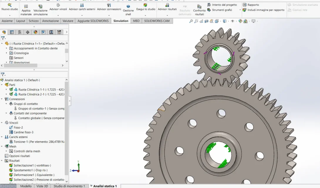
what I kindly ask you, are clarifications or confirmations on my procedure in defining constraints and forces in the simulation environment of solidworks (linear static analysis). after defining the materials created by me (I did not find them in the default library) I imposed as constraints, a pinion pin (the wheel on which I applied then the torque) and the wheel conducted I made it fixed. both the torque and the constraints I applied them on the inner face that would go in contact with the tree (allego screen).

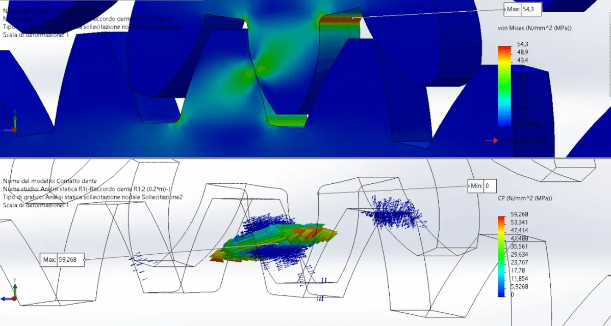
According to your opinion, could this model approach me to the analysis of contact according to hertzian theory, being aware that it is not the best?

If I may not have been very clear, I can relay the whole even more in detail.

thanking anyone who will answer me in advance,
I wish everyone a good continuation of the day.
 

Attachments

  • Annotazione 2020-07-25 130637.webp
    Annotazione 2020-07-25 130637.webp
    72.9 KB · Views: 44
  • Annotazione 2020-07-25 130756.webp
    Annotazione 2020-07-25 130756.webp
    88.4 KB · Views: 42
I can't use it and I can't read the simulations, but it seems strange that there is nothing between all the materials that suits you. gears are made with steels such as those indicated in This post which are both present in the default library as you see from the image. these are the most common materials on the market, but if you use a slightly different material does not change the result
 

Attachments

  • Immagine.webp
    Immagine.webp
    65.6 KB · Views: 39
in the very first approximation yes.... is correct.
However, I see that the tooth model is made with toolbox and therefore it is not true that the bottom is a circle....maintain the background rays due to the creator (unless the revenues of electro-erosion or sintered metal casting).
Besides the material library of solidworks is very rich....in what materials have you made are blessed gears?
then you will have to make a very fine mesh in contact and it is not easy to really shape the contact.
besides the fact that the evolved is not real but approximated.
 
I would also improve background rays as mentioned by mechanicalmg. then make a simple mesh except in the teeth, where I would go to make it more thick especially in the rays. Also since it is a thesis, you could try to make a comparison using symmetry, so explain with what difference the two solutions converge towards the result.
 
Thank you for the prompt answers!
As for the material, my prof. provided us with a list of materials that we could use, I chose therefore, based on verification to wear and fatigue (made with lewis), for the cylindrical gear a 42crmo4 reclaimed (that in fact I had found on solidworks but did not have the same sigma of breakage and ribbing), while for conical gearing11 I chose a 16 cement library not found.
in the very first approximation yes.... is correct.
lack the basic rays due to the creator

then you will have to make a very fine mesh in contact and it is not easy to really shape the contact.
besides the fact that the evolved is not real but approximated.
I am aware of this question, in fact I have applied mesh control only on the faces of the tooth, but I believe that I will draw it further. for the fittings, I will apply them and it is a speech that I will address in the thesis regarding hotspots and singularities
 
I should now perform the same analysis for conical wheels, do you think I can do the same procedure? I apologize if I ask you too much, but is my first approach to analysis unfortunately not followed by experts?
 
I'll get you a document that could give you some inspiration.
Keep in mind that if teeth are rectified you may have a small defect that intensifies the effort.
I also believe light a compound of actions/reactions and not exactly a contact of hertz and a flexional sigma at the base of the tooth.
conical wheels can also be handled the same way.
 

Attachments

I thank you for the annex, which I had already found on the net. It's too detailed for the treatment I have to do, but I'll keep in mind. Unfortunately I have to arrange with solidworks because I have this software.
I also believe light a compound of actions/reactions and not exactly a contact of hertz and a flexional sigma at the base of the tooth.
conical wheels can also be handled the same way.
Yes, the stresses are quite "sporty", perhaps I should use the "contact pressure" diagram that displays the vectors (?).
my idea for the bending analysis of the tooth was to take the pinion individually and impose fixed bond on the axis and total force ( resulting between tangential and radial force) applied on the tooth. Could it be a right approach?
 
I thank you for the annex, which I had already found on the net. It's too detailed for the treatment I have to do, but I'll keep in mind. Unfortunately I have to arrange with solidworks because I have this software.

Yes, the stresses are quite "sporty", perhaps I should use the "contact pressure" diagram that displays the vectors (?).
my idea for the bending analysis of the tooth was to take the pinion individually and impose fixed bond on the axis and total force ( resulting between tangential and radial force) applied on the tooth. Could it be a right approach?
to put total force on the individual tooth you need to correctly locate the point or place of force application points and then direction. If you can... ..it would be optimal, but it is quite laborious to do it properly. Also you must break the tooth surface with a line to apply the load.
But then... do you work only a couple of teeth?
 
I understood, I imagined it would be more laborious than expected. I will try to make some approximations that I will discuss.
But then... do you work only a couple of teeth?
Yes, in the project and for how we sized the gears, it took only 1 pair of teeth in socket. I know that it is very primordial as what, but having used only lewis and hertz and a proportion of the normal tooth, these are the results. Unfortunately, in the three-year university programme, there was only a discussion about the size and the agma standard (in my opinion reduced).
 
good evening to all, sorry if I write also on Sunday, but I wanted to show myself my results about it, after having made a basic chord to the tooth (rough = 0.2*module, in my case being wheels module 6 mm, the radius I made of 1.2 mm). In addition, I put the mesh before manually with a mesh control, and then I applied an adactive h-adactive control, with 5 iterations. I read on the net that this method automatically affects the mesh where it serves. in fact I noticed the differences in the results. I noticed the most relevant differences in the contact pressure diagram. the first image is without h-adactive, the second is with h-adactive.
image with mesh data refers to the first case. I don't know why it automatically created a mesh based on curvature. for you who are more experienced is better than standard mesh?
if you have any opinion, advice or interpretation of data, they are well accepted.

I wish everyone a good evening.
 

Attachments

  • Contatto dente-Analisi statica R1-Immagine-1.webp
    Contatto dente-Analisi statica R1-Immagine-1.webp
    82.1 KB · Views: 33
  • Contatto dente-Analisi statica Mesh st-Immagine-1.webp
    Contatto dente-Analisi statica Mesh st-Immagine-1.webp
    75.4 KB · Views: 32
  • Annotazione 2020-07-26 191402.webp
    Annotazione 2020-07-26 191402.webp
    150.8 KB · Views: 29
How are the hand calculations compared to the fem?
if you want you can post geometric features of gears and power/shifts of operation, so we see the numbers that turn.
of each gear serves:
- form
- tooth number
- helical angle and pressure
- x profile shift
- interasse
- arrangements
- power or torque
- material and treatment
Mesh based on curvature to suit better geometry therefore more adherent to geometries with section variations than standard mesh. the h or p adaptive method is a little menata to check the correctness of the result. can converge but not to the true result. I don't really use it. You should go study the theory a bit and see how to handle it and have a small residue and then go to a truthful solution.
from the mesh report seems a little big....2mm the small mesh with module 6....the contact area I would wait for it with mesh 0.5.
I remember that standard teethers have background radius 0.25*m and 0,375*m. the value of 0.2*m is very little used and is more sensitive to carvings.... besides not finding the curves of ys and yf on the concentration of effort. I recommend using 0,375*m.

.... did the forum not sabati/domeniche/feste??? ?
 
Last edited:
First of all, congratulations on the subject of thesis : so first of all there is to apply hertzian theory with the classic theoretical formula. Once you have the numerical data you can proceed with the model building (usually if you get a 3% error you can feel more than satisfied). the most inflating in the contact points from a more truthful result (what in more spindles analysis are created rectangle meshatures around the contact points)
1595794675402.png1595794704202.pngI'll put you a document that might help you.
for bond conditions you should be ok. Most manufacturers use simplified models (2d) or however limit the analysis to a smaller number of teeth to reduce the computational weight of the model.

the h-adaptation analysis you need to understand if you are going in convergence with the mesh value, increasing the mesh knots to each loop..
if you have a divergence (as in the case of singularities, living images etc.), stress comes to infinite values and therefore at each step the program increases the value of the sigma of von mises-
with the p-adaptation at each stage the nodes of the elements are increased (not the number of knots). .

at least this is that of memory, but I do not use solidworks for long.. who uses it will know to tell you more;)
 
Thank you for your time.
I would like to congratulate the rapporteur on his work.
I also thank you for your compliments, let's say that the thesis is not directly centered on the dente-dent contact, but it starts from the sizing of maximum of a railway reducer to orthogonal axes and from here analyze to the pc through analysis fem the sizing trees (you also have doubts about the analysis of the trees, maybe if I can, without opening another tread, we can talk here). Afterwards, my rapporteur said that we could also analyse the contact between teeth. now on this I try to respond to mechanicalmg. Frankly I wouldn't have hand-made calculations regarding tooth contact, so I don't know what to compare the data I spit on solidworks. the only calculations made are those of fatigue testing and surface fatigue (wear) calculating the safety coefficients (magari li allego below). I believe that my rapporteur would like to do a qualitative analysis without going into numerical details. But speaking via email with prof. is it really difficult?.
Now place the characteristics of the complete reducer (I also attach the unifilare pattern) so we can talk about numbers. being cylindrical wheels with straight teeth the angle of helix is 0, that of pressure is 20°. the rest is in the summary table for both conical and cylindrical gearing. the profile has not been moved and the teeth is normal (addendum=module; dedendum=1.25*a)
to do before, I attach an extract of my thesis (it is the initial part of the sizing)
I remember that standard teethers have background radius 0.25*m and 0,375*m. the value of 0.2*m is very little used and is more sensitive to carvings.... besides not finding the curves of ys and yf on the concentration of effort. I recommend using 0,375*m.
I will keep this in mind. Thank you. Unfortunately we have not deepened the basic chord so I chose a dimension that I felt appropriate.
Mesh based on curvature to suit better geometry therefore more adherent to geometries with section variations than standard mesh. the h or p adaptive method is a little menata to check the correctness of the result. can converge but not to the true result. I don't really use it. You should go study the theory a bit and see how to handle it and have a small residue and then go to a truthful solution.
from the mesh report seems a little big....2mm the small mesh with module 6....the contact area I would wait for it with mesh 0.5.
So from what you're telling me, you recommend me the mesh on curvature but choosing the size of the reduced elements? the size that reads in the report I chose her to have a thick mesh but with not many elements. with mesh control on the teeth I reduced the size to 1.5 mm. Maybe tomorrow I try with 0.5 mm as recommended by her.
the h-adaptation analysis you need to understand if you are going in convergence with the mesh value, increasing the mesh knots to each loop..
if you have a divergence (as in the case of singularities, living images etc.), stress comes to infinite values and therefore at each step the program increases the value of the sigma of von mises-
with the p-adaptation at each stage the nodes of the elements are increased (not the number of knots). .
in fact, every time an iteration ended, it increased the maximum value of the von-mises voltage and then checking the chart, the method did not go to convergence. Unfortunately I did not want to increase iterations because it already took a half hour to carry out 5, I would not like to imagine how long it would take to carry out more. I didn't try p-adactive at all.
I repeat I am approaching for the first time and alone to fem analysis (maybe not with the most indicated software) so I do not know how to interpret the various methods and evaluate if the analysis is correct. By linking me to this I carried out the analyses also on the trees, and the only comparisons I could have are in the binding reactions of the beam that I solved by hand and unfortunately I am not very much. But I would like to take a step at a time and discuss it after trees.

Thank you again for the support given me.
 

Attachments

  • Annotazione 2020-07-27 010457.webp
    Annotazione 2020-07-27 010457.webp
    38.3 KB · Views: 27
  • Estratto.pdf
    Estratto.pdf
    2.7 MB · Views: 16
I read the data you posted and I find a small question.
Let's talk about cylindrical wheels, so the first stage.
you used 42crmo4 remediation material from pre-bonified bar. But you're not tempting your teeth? leave only tempering and standard tempering? or do you reclaim to heart and impose hardness?
I'm telling you this because I feel a little soft without hardening on my teeth... But it can be.

bending, the tensions that develop at the base of the tooth according to iso6336 are around 67mpa for the pinion and 55mpa for the wheel. instead for contact on the tooth side we have about 922mpa on the pinion and 800mpa on the wheel.
I met your values of "work" which are very close to the values I just wrote and this is good sign.
Now, with the fem you have to find these values, ±3% perfect....±5% good....±10% better....≥10% is not good.
Another thing.... the cover is 1.6 so it means that it works more than one tooth in socket and in theory you should see the head of the other tooth work partially and the bottom of the third tooth just touched by contact.

As for the trees and reactions, are you sure that by hand they are right? check them with ftool which is free, so you will read the doubt.

fems and trees.... surely carvings, fittings, interaction components can make vary locally even so much the result. However you can estimate with manual calculation.
a colleague of yours did a post where he had as an exercise to make fems on actions made up of trees with carvings and see how the fem calculated correctly or not the value (unfortunately not all cases took the theoretical value correctly).
 
Last edited:
I read the data you posted and I find a small question.
Let's talk about cylindrical wheels, so the first stage.
you used 42crmo4 remediation material from pre-bonified bar. But you're not tempting your teeth? leave only tempering and standard tempering? or do you reclaim to heart and impose hardness?
I'm telling you this because I feel a little soft without hardening on my teeth... But it can be.
Thank you so much for your time. for the material, there were tables with those hardnesses. I then found a technical sheet of that steel and the hardnesses didn't match. I believe that in that table a hardening on the teeth is undermined to increase the hardness on the tooth (on the technical sheet I have a 270 hb, mind the characteristics given by Prof indicate 530hb). If you tell me you have to do these treatments, I'm gonna put them in the treatment.
bending, the tensions that develop at the base of the tooth according to iso6336 are around 67mpa for the pinion and 55mpa for the wheel. instead for contact on the tooth side we have about 922mpa on the pinion and 800mpa on the wheel.
I met your values of "work" which are very close to the values I just wrote and this is good sign.
Now, with the fem you have to find these values, ±3% perfect....±5% good....±10% better....≥10% is not good.
Another thing.... the cover is 1.6 so it means that it works more than one tooth in socket and in theory you should see the head of the other tooth work partially and the bottom of the third tooth just touched by contact.
Here, with regard to the bending, we have never applied this norm. Therefore, precisely because I have to analyze the tooth and follow the calculation, so that I have responded with the fem. I do not understand the question of replenishment. Could you please explain it to me?
As for the trees and reactions, are you sure that by hand they are right? check them with ftool which is free, so you will read the doubt.

fems and trees.... surely carvings, fittings, interaction components can make vary locally even so much the result. However you can estimate with manual calculation.
a colleague of yours did a post where he had as an exercise to make fems on actions made up of trees with carvings and see how the fem calculated correctly or not the value (unfortunately not all cases took the theoretical value correctly).
the trees I have solved them with ftool as well as by hand, and with the calculations I find myself. I can attach them under. Would you kindly link my colleague's post? Maybe I could get rid of the doubts by reading it instead of asking the same things that you've already talked about.
Basically, I'm afraid that something is wrong in the definition of forces and how they are applied in the model on solidworks. The only tree I've got in the fem model is the input shaft.

to some advice or notation, however, regarding conical wheels?

Thank you very much for your availability! :d
 

Attachments

First of all, don't give me some of her. ? ?

I used iso 6336 but you used the agma norm and got more or less the same values. this to tell you that the hand calculation is right and provides you with just bending pressure and tension. must be proven by fem....or better....you have to turn the fem and see if you can get the same results without making the wrong assumptions.

exactly the material you used must have a hardening on your teeth or a second rectification with higher durability..... otherwise it is as soft as iron.

the discussion on carvings and fem is qui.

Unfortunately the conical wheels are not my passion, but I noticed that:
- the width b can not be so different and you probably took all the cone and not the useful. in fact the useful band will be the minimum of 29mm.
- the calculated values of pressure and force are very similar to those calculated by you so they are just
- for the fem you have to do the same thing with cylindrical wheels.
 
It was not my intention to trade her for woman: lol: from now on I give you some.

In essence iso 6336, I was already trying to make calculations, it is an alternative to the Agma rule, which, if you pass the term, is more primordial. I noticed that iso 6336 introduces more coefficients and shape factors.
I am relieved that the values correspond using two different norms, it is the first time I have such a comparison and it is a nice feeling.
for the conical wheels... then it is thought, I would not want the treatment to be repeated if I make the same speech of the cylindrical wheels.
seized the speech on steel (y).
I don't know if you looked at the second extract, but I think I'm wrong with solidworks. Maybe tomorrow I show up, posting some screens of my definitions of forces and constraints. I will also read my colleague's post, thanks to the link!
Now I think we're all tired?
I wish everyone a good night.
 
That's what I didn't answer.
This parameter indicates how many teeth in the socket are. Since there are teeth in grip, it turns out better strength and less working game if I make inversions, if I have a factor of repletion greater than two. I will clearly have a little more wear. if I use helical wheels I also have the covering due to the propeller and for example I can use important angles to significantly improve the transmission of the total motion.
 

Forum statistics

Threads
44,997
Messages
339,767
Members
4
Latest member
ibt

Members online

No members online now.
Back
Top