Sebastiano71
Guest
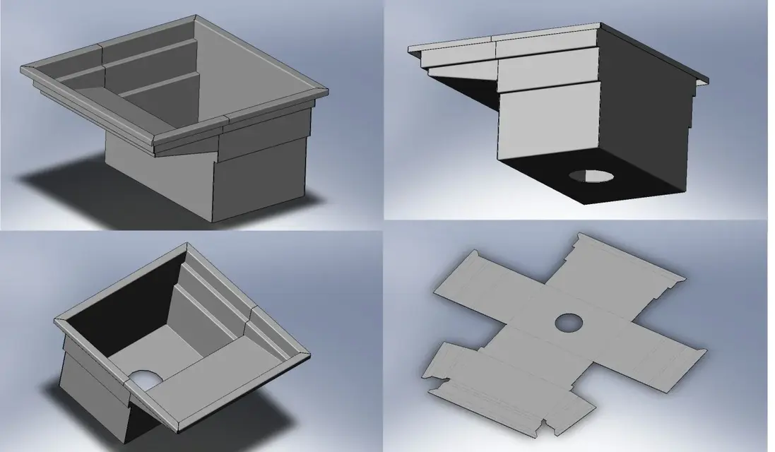
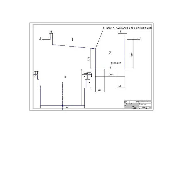
Hello, everyone. I would like to underwent my riddle, that is the construction in a tub sheet. I attached a file in 2d of massiam only to understand what shape it has. as you see for constructive reasons, I numbered the slip with number 1 and the tray with hole n.2, because both of them get with separate sheets and then welded where I put the welding note. I come to the qunque; I tried in several ways it has to make the slip (1), even with a loft, but I did not succeed (me by mistake). If I build it with the usual functions of flanges and edges/angles after I can't close the corners, then the profile remains open. I also can't put the slippery plan.
Who can give me any ideas?
Thank you.
Who can give me any ideas?
Thank you.
 it will be because where I work we are for simple things simple and rather to put a more fold we try to put 2 in less:tongue:
") I understand what Sebastiano asks.
I understand what Sebastiano asks.