• This forum is the machine-generated translation of www.cad3d.it/forum1 - the Italian design community. Several terms are not translated correctly.

angle reference design

  • Thread starter Thread starter np426
  • Start date Start date
I checked the lengths of the trees and they're both 42mm, down to 35?
as tabs I chose a 14mm long 4x4 for the incoming tree and a lowered tab (if I had used a normal tab I would not have satisfied the verification of the tree as the t1 lowered me too the useful diameter) 5x3 18mm long
for the length of the quarry are not clear to me the size, for the tabs that I have chosen are good respectively the lengths of 16mm and 20mm? How much do I detach the beginning of the quarry from the end of the tree? 10mm is enough?
 
I checked the lengths of the trees and they're both 42mm, down to 35?
as tabs I chose a 14mm long 4x4 for the incoming tree and a lowered tab (if I had used a normal tab I would not have satisfied the verification of the tree as the t1 lowered me too the useful diameter) 5x3 18mm long
for the length of the quarry are not clear to me the size, for the tabs that I have chosen are good respectively the lengths of 16mm and 20mm? How much do I detach the beginning of the quarry from the end of the tree? 10mm is enough?
I try to answer the questions.

the tabs must be verified and in the context also tree and hub. If you work with steels with high mechanical characteristics like 42crmo4 instead of c45 ...for shaft and hub you can have higher tensions.
the niemann clearly says, in addition to the experience not only mine, a signa of 100mpa is normal. if the materials are of quality and the non-trade tabs but built in hardened materials you can reach 200mpa.

I think you're using the proposed method qui.

for tab verification, hub seat and tree I recommend you look This is post. clearly rs will be of the element in verification.

tab offices can also be 1mm away from the edge and depending on the size you can climb (10mm are per tab for 50-60mm trees. on small diameter it is less). clearly that certain geometries risk the departure of cracks.
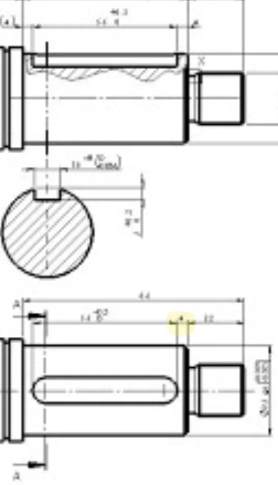
Screenshot_20240825_195405_Chrome.webpcan also be open frontally if you make it necessary in short lengths to start the tongue edge immediately and then maximize the useful length of flow.

the long tree with stretch without tongue does not serve anything, so either stretch the tabs or shorten the trees.
if you look at commercial gearboxes, in their catalogs you will see that the proportions are more "great"
 
I try to answer the questions.

the tabs must be verified and in the context also tree and hub. If you work with steels with high mechanical characteristics like 42crmo4 instead of c45 ...for shaft and hub you can have higher tensions.
the niemann clearly says, in addition to the experience not only mine, a signa of 100mpa is normal. if the materials are of quality and the non-trade tabs but built in hardened materials you can reach 200mpa.

I think you're using the proposed method qui.

for tab verification, hub seat and tree I recommend you look This is post. clearly rs will be of the element in verification.

tab offices can also be 1mm away from the edge and depending on the size you can climb (10mm are per tab for 50-60mm trees. on small diameter it is less). clearly that certain geometries risk the departure of cracks.
View attachment 71917can also be open frontally if you make it necessary in short lengths to start the tongue edge immediately and then maximize the useful length of flow.

the long tree with stretch without tongue does not serve anything, so either stretch the tabs or shorten the trees.
if you look at commercial gearboxes, in their catalogs you will see that the proportions are more "great
the second link does not work, it gives me error.
after I notice the distances of the premises and try to make the checks. not knowing anything about the incoming and outgoing joints can I do it anyway? I chose tabs according to the diameter of the tree, the length I had taken it to "eye".
 
the second link does not work, it gives me error.
after I notice the distances of the premises and try to make the checks. not knowing anything about the incoming and outgoing joints can I do it anyway? I chose tabs according to the diameter of the tree, the length I had taken it to "eye".
proof Who. links for tabs. alternatively search on cad3d .
the joint that will be there you do not know but reasonably you will choose something capable of bringing the couple.
the length should be calculated and if ever stretched.
 
proof Who. links for tabs. alternatively search on cad3d .
the joint that will be there you do not know but reasonably you will choose something capable of bringing the couple.
the length should be calculated and if ever stretched.
I made the sizing of the tabs following those calculations and everything is verified, I shortened the length of the tab of the input shaft bringing it from 14 to 10mm (because it had to be >=2,6mm), shortened again the trees and approached the end of the quarry at the beginning of the tree.
 
I'm starting the harvest, I don't have much experience about it. . .especially for geometric tolerances.
Do you have any advice on this? wrinkles I still need to insert them
 

Attachments

  • 1.webp
    1.webp
    34.8 KB · Views: 20
I'm starting the harvest, I don't have much experience about it. . .especially for geometric tolerances.
Do you have any advice on this? wrinkles I still need to insert them
for this look previous discussion.

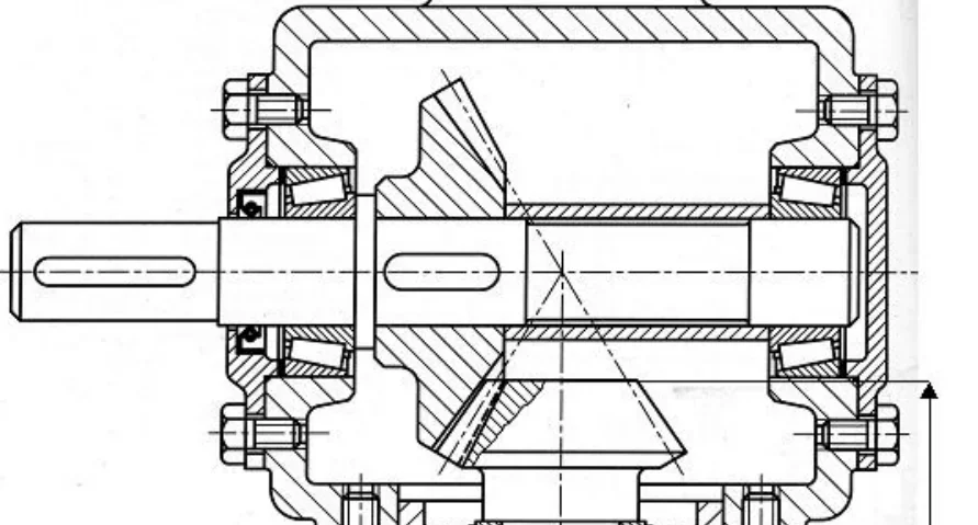
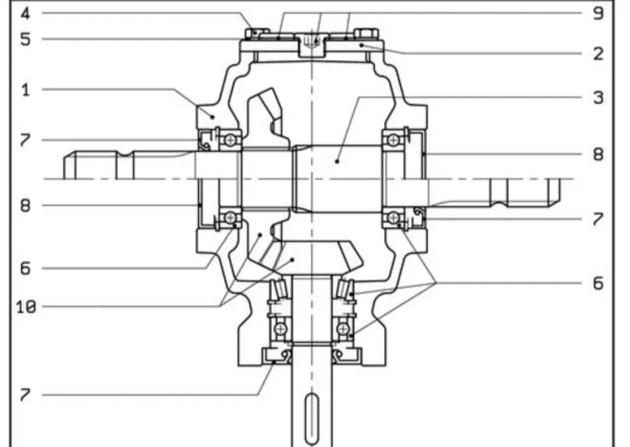
As far as the rest is concerned, at a time when the debate has already been widely evaluated and commented, but there are some particularities I would like to highlight; In this regard I attach a document to support my observations in which an example of an industrial angular reference is reported (gleason pair, no to rights teeth) with characteristics similar to those you indicated initially. differs from your morphological reference as that structure has to offer the possibility to have more reduction reports and more versionisms, as you can notice (in the exploded) also from the exit shaft with a hollow for long tongue in order to be able to mount the crown to the left or to the right changing in this way the direction of rotation in exit.
- observing your design I must point out that incoming shaft bearing support fits well with flange; where @meccanicamg rightly suggested that you use to interpose thicknesses but what brings the sealing ring is superfluous as the seat of the sealing ring can be obtained on the flanged support itself.
- another observation concerns the input shaft, for which I have given you some indications on the lengths according to the diameter; Of course they are indicative because, not being standardized, there may be slight differences between the products of the various manufacturers.
you need to review the line with the 30* bevel (see example in the attached document) and the shaft rectification discharge between the two bearing sites for which it is sufficient to predict a diameter less than 1 mm than the diameters of the two seats.
- with regard to the exit part, as you have conceived, in my opinion it is almost impossible to record the conical crown because every time you should reassemble everything, so it is to be reviewed; observe your design and try to hypothesize where and how you would mount the thicknesses to move the conical crown to the left or right.
 

Attachments

for this look previous discussion.

As far as the rest is concerned, at a time when the debate has already been widely evaluated and commented, but there are some particularities I would like to highlight; In this regard I attach a document to support my observations in which an example of an industrial angular reference is reported (gleason pair, no to rights teeth) with characteristics similar to those you indicated initially. differs from your morphological reference as that structure has to offer the possibility to have more reduction reports and more versionisms, as you can notice (in the exploded) also from the exit shaft with a hollow for long tongue in order to be able to mount the crown to the left or to the right changing in this way the direction of rotation in exit.
- observing your design I must point out that incoming shaft bearing support fits well with flange; where @meccanicamg rightly suggested that you use to interpose thicknesses but what brings the sealing ring is superfluous as the seat of the sealing ring can be obtained on the flanged support itself.
- another observation concerns the input shaft, for which I have given you some indications on the lengths according to the diameter; Of course they are indicative because, not being standardized, there may be slight differences between the products of the various manufacturers.
you need to review the line with the 30* bevel (see example in the attached document) and the shaft rectification discharge between the two bearing sites for which it is sufficient to predict a diameter less than 1 mm than the diameters of the two seats.
- with regard to the exit part, as you have conceived, in my opinion it is almost impossible to record the conical crown because every time you should reassemble everything, so it is to be reviewed; observe your design and try to hypothesize where and how you would mount the thicknesses to move the conical crown to the left or right.
Good morning.
Thank you very much for the answer.
yes you are right, proceed to the removal of flanged cap and use a seeger for the locking of the bearing and a larger oil.
for unloading between the bearing seats (hole diameter 15mm) so I should raise the shaft diameter to 13mm and make a r1 connection?
for the crown registration, I thought I was playing with the spacer and the correction (or possible thickness) of the circular extrusion behind the wheel that makes as a shouldering on the tree. .
What do you recommend?
 
I should also remove the cap that does from shouldering to the bearing of the shaft duct, put a seeger and as a cap a similar to This is ?
or put a screw cap opposite to the one already existing, so as to allow the registration of the wheel as in the proposed example qui
 
for unloading between the bearing seats (hole diameter 15mm) so I should raise the shaft diameter to 13mm and make a r1 connection?
Yes, even if a line on the protruding shaft of 0.5 mm (15-14)/2 does not like much because to have a decent bar you should apply a thick shaving ring a pair of mm with live edge in the bare side hole.
However it leaves so, considering that the coupling to the engine will most likely be carried out by joint, it is not necessary that the semi-joint reference side should go to line. But remember that in the case of trees where a pulley or pinion could be applied, it is useful to predict a larger line (e.g. on the outgoing tree).
for the crown registration, I thought I was playing with the spacer and the correction (or possible thickness) of the circular extrusion behind the wheel that makes as a shouldering on the tree. .
no, because you should proceed for attempts by disassembling every time the whole slow part which, although technically it is possible, from the practical point of view is not admissible.
I should also remove the cap that does from shouldering to the bearing of the shaft duct, put a seeger and as a cap a similar to This is ?
if you block the bearings with the seeger you can close with two caps of the type you refer to; in this case avoid the construction of lids using these commercial components at a much lower cost.
or put a screw cap opposite to the one already existing, so as to allow the registration of the wheel as in the proposed example qui
can go well, some manufacturers use that solution (the designation normally used is: closing cover) which facilitates registration.
compared to the above caps have the advantage of not requiring a press to apply the preload.
for sealing these covers it is not necessary to apply o-ring rings or seals, it is sufficient to use a specific loctite 510 sealer on the contact planes (it does not thickness, unlike the seals for which it is generally considered a thickness of 0.5 mm).
Obviously it is applied when the recording is finished.

with regard to the amount of lubricant, in the presence of a transparent cap, you can keep the level at such a height that covers the balls or rollers of the bearings; the speed is high enough to lubricate also the engraving area and bearings of the input shaft, as long as the reference is placed in horizontal position b3.
as a lubricant it is advisable a synthetic oil with viscosity iso vg 220 which, compared to mineral-based lubricant, allows the change at more spaced intervals. in addition to the level cap you will also have to include one with vent for filling and one closed in the lower (but accessible) part of the reference in order to carry out the discharge without having to uninstall the postponement itself.
 
Yes, even if a line on the protruding shaft of 0.5 mm (15-14)/2 does not like much because to have a decent bar you should apply a thick shaving ring a pair of mm with live edge in the bare side hole.
However it leaves so, considering that the coupling to the engine will most likely be carried out by joint, it is not necessary that the semi-joint reference side should go to line. But remember that in the case of trees where a pulley or pinion could be applied, it is useful to predict a larger line (e.g. on the outgoing tree).

no, because you should proceed for attempts by disassembling every time the whole slow part which, although technically it is possible, from the practical point of view is not admissible.

if you block the bearings with the seeger you can close with two caps of the type you refer to; in this case avoid the construction of lids using these commercial components at a much lower cost.

can go well, some manufacturers use that solution (the designation normally used is: closing cover) which facilitates registration.
compared to the above caps have the advantage of not requiring a press to apply the preload.
for sealing these covers it is not necessary to apply o-ring rings or seals, it is sufficient to use a specific loctite 510 sealer on the contact planes (it does not thickness, unlike the seals for which it is generally considered a thickness of 0.5 mm).
Obviously it is applied when the recording is finished.

with regard to the amount of lubricant, in the presence of a transparent cap, you can keep the level at such a height that covers the balls or rollers of the bearings; the speed is high enough to lubricate also the engraving area and bearings of the input shaft, as long as the reference is placed in horizontal position b3.
as a lubricant it is advisable a synthetic oil with viscosity iso vg 220 which, compared to mineral-based lubricant, allows the change at more spaced intervals. in addition to the level cap you will also have to include one with vent for filling and one closed in the lower (but accessible) part of the reference in order to carry out the discharge without having to uninstall the postponement itself.
the diameter of the external input shaft is 12mm not 14, I sized it and checked it and I'm in it. I want to do it of 13, so I have beveled of 1mm accurate.
the purging cap I put it in the lower part under the sprocket, while for the rabble, having the high cap I thought to put it from there the oil...
 
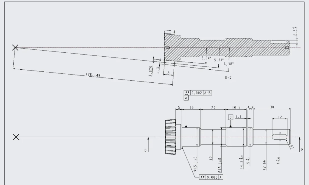
I'm starting the harvest, I don't have much experience about it. . .especially for geometric tolerances.
Do you have any advice on this? wrinkles I still need to insert them
the ingutta seat does not quote r2 but you will have to quota width 4 and with its tolerance.
 
the ingutta seat does not quote r2 but you will have to quota width 4 and with its tolerance.
width 4 with relative tolerance 0 and -0,03 by manual is already present in the table, I did not know it was not to put the connection... I read it immediately,
Thank you.

regarding the use of the 2 plugs that support the bearings (with rectifying spacer interposed? by how I interpreted the drawing) for the recording of the crown... can I adopt the same method despite the ball bearings? doing so falls the hypothesis of having a zipper and a cart?
 

Attachments

  • Screenshot (87).webp
    Screenshot (87).webp
    45.5 KB · Views: 15
Last edited:
for this look previous discussion.

As far as the rest is concerned, at a time when the debate has already been widely evaluated and commented, but there are some particularities I would like to highlight; In this regard I attach a document to support my observations in which an example of an industrial angular reference is reported (gleason pair, no to rights teeth) with characteristics similar to those you indicated initially. differs from your morphological reference as that structure has to offer the possibility to have more reduction reports and more versionisms, as you can notice (in the exploded) also from the exit shaft with a hollow for long tongue in order to be able to mount the crown to the left or to the right changing in this way the direction of rotation in exit.
- observing your design I must point out that incoming shaft bearing support fits well with flange; where @meccanicamg rightly suggested that you use to interpose thicknesses but what brings the sealing ring is superfluous as the seat of the sealing ring can be obtained on the flanged support itself.
- another observation concerns the input shaft, for which I have given you some indications on the lengths according to the diameter; Of course they are indicative because, not being standardized, there may be slight differences between the products of the various manufacturers.
you need to review the line with the 30* bevel (see example in the attached document) and the shaft rectification discharge between the two bearing sites for which it is sufficient to predict a diameter less than 1 mm than the diameters of the two seats.
- with regard to the exit part, as you have conceived, in my opinion it is almost impossible to record the conical crown because every time you should reassemble everything, so it is to be reviewed; observe your design and try to hypothesize where and how you would mount the thicknesses to move the conical crown to the left or right.
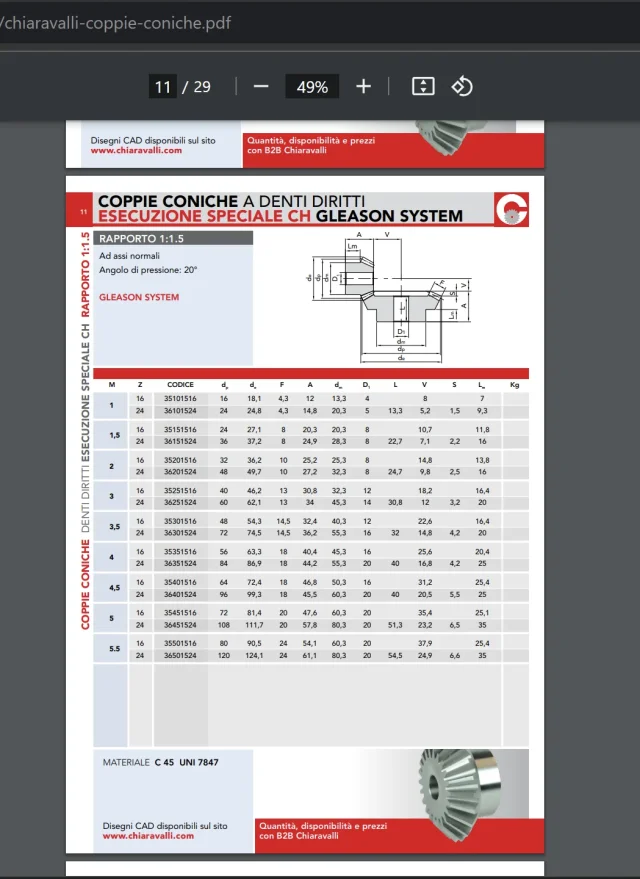
I found the table of the reducer for agricultural use that you recommended me in the pdf annex, the allego below. I don't think there's any methods to record wheels, do I?
 

Attachments

  • Screenshot (88).webp
    Screenshot (88).webp
    25 KB · Views: 13
regarding the use of the 2 plugs that support the bearings (with rectifying spacer interposed? by how I interpreted the drawing) for the recording of the crown... can I adopt the same method despite the ball bearings?
Yes, it is commonly adopted method in standard low and medium power industrial gearboxes.
generally there are no rectifying spacers but commercial rings with variable thicknesses of the order of tenths of millimeter.
doing so falls the hypothesis of having a zipper and a cart?
in this case yes; the conical bearings are preloaded and the ball bearings must have the axial assembly equal to zero. the temperature will surely produce expansions that will determine a precarious even in the ball bearings, but being of reduced dimensions with modest loads the extent of such axial loads induced by the expansions will be however limited and acceptable.
different is the speech for gearboxes for special applications (e.g. rolling mills and billet rollers) or larger dimensions for which the concept of hinge-carrello is to be considered because of the effects produced by the severe operating conditions.
I found the table of the reducer for agricultural use that you recommended me in the pdf annex, the allego below. I don't think there's any methods to record wheels, do I?
in the calculation of the chain of tolerances a minimum of play is always foreseen to be recovered with the thickness mentioned above but, generally, being able to be or not present are not represented in the overalls as also the quantity and thicknesses vary according to the requirements of that assembly and the processing tolerances obtained.

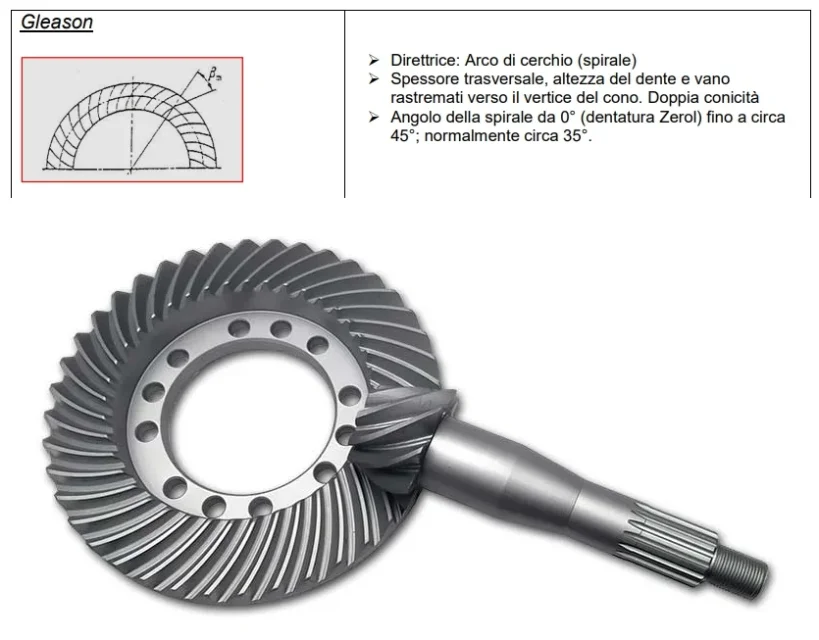
for your information, it is also necessary to specify that the reducer I have indicated to you, of which you have published the total, finds application in the agricultural sector (semoventi, trebbiatrici, etc.) and uses straight toothed conical gears, a feature that makes them cheaper but also a bit noisy compared to rectified gleason conical pairs used in gearboxes for the industrial sector; this, of course, because in agricultural machines the inlet speed is generally low (strength or hydraulic motor) and then because the prevailing noise determined by the endothermic engines surely covers that of the reducer that being in open field is less perceptible.
 
Yes, it is commonly adopted method in standard low and medium power industrial gearboxes.
generally there are no rectifying spacers but commercial rings with variable thicknesses of the order of tenths of millimeter.

...

in the calculation of the chain of tolerances a minimum of play is always foreseen to be recovered with the thickness mentioned above but, generally, being able to be or not present are not represented in the overalls as also the quantity and thicknesses vary according to the requirements of that assembly and the processing tolerances obtained.

for your information, it is also necessary to specify that the reducer I have indicated to you, of which you have published the total, finds application in the agricultural sector (semoventi, trebbiatrici, etc.) and uses straight toothed conical gears, a feature that makes them cheaper but also a bit noisy compared to rectified gleason conical pairs used in gearboxes for the industrial sector; this, of course, because in agricultural machines the inlet speed is generally low (strength or hydraulic motor) and then because the prevailing noise determined by the endothermic engines surely covers that of the reducer that being in open field is less perceptible.
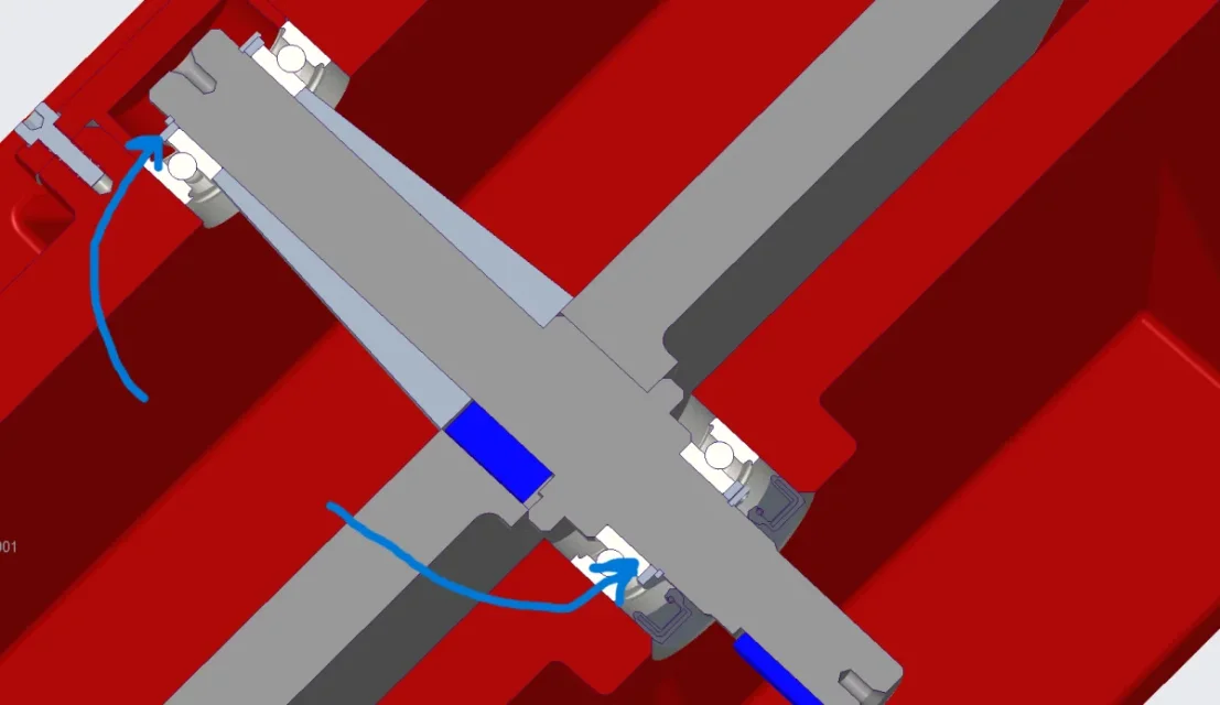
so I just have to use variable thicknesses (these would it be okay?) instead of the classic washers put where I indicated with the blue arrow in the attached photo, to get the same result? it seems more comfortable so that using the double stopper (at this point I would also remove the top cap to put what we talked about yesterday in gasket)

What are gleason couples? even my gearbox is using straight teeth conical gears, we were imposed by prof.
 

Attachments

  • Screenshot (89).webp
    Screenshot (89).webp
    35.1 KB · Views: 16
Last edited:
so I just have to use variable thicknesses (these would it be okay?) instead of the classic washers
sì.
where I indicated with the blue arrow in the attached photo, to get the same result right?
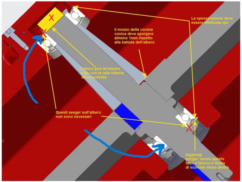
No. look at the annotations on the attached image.

you can also replace the cover with screws with the closure cap but you have to predict another seeger holding the outer ring of the bearing.
 

Attachments

  • Insieme blocco uscita.webp
    Insieme blocco uscita.webp
    68 KB · Views: 14
see attached pictures and watch this document that illustrates the various types of conical teeth and can be useful to you.
perfect thanks, I knew you used the term to indicate the spiral ones but then I found This is pdf that uses gleason also for those conics with straight teeth and I got the doubt.
 

Attachments

  • Screenshot (96).webp
    Screenshot (96).webp
    90.5 KB · Views: 5
Yes.

No. look at the annotations on the attached image.

you can also replace the cover with screws with the closure cap but you have to predict another seeger holding the outer ring of the bearing.
Thank you very much for the photo, I extended the tree because I thought the hole for the lathe reduced the useful section creating problems on the bearing.
As for internal seegers, I read them immediately and add the external one with its recording thicknesses.
 
Last edited:

Forum statistics

Threads
44,997
Messages
339,767
Members
4
Latest member
ibt

Members online

No members online now.
Back
Top