np426
Guest
What is the cast iron that is used to make the box? I need it for bom
ra1.6 I would say that it is more than good for the envelope parcel tree input.Good evening,
I am continuing with the harvests at the table, which mating is advisable between the hole of the box and the sprocket package? 1,6 on both can it be okay?
always for sprocket-box package, as o-ring I chose This is but I do not find anywhere the size of its seat.
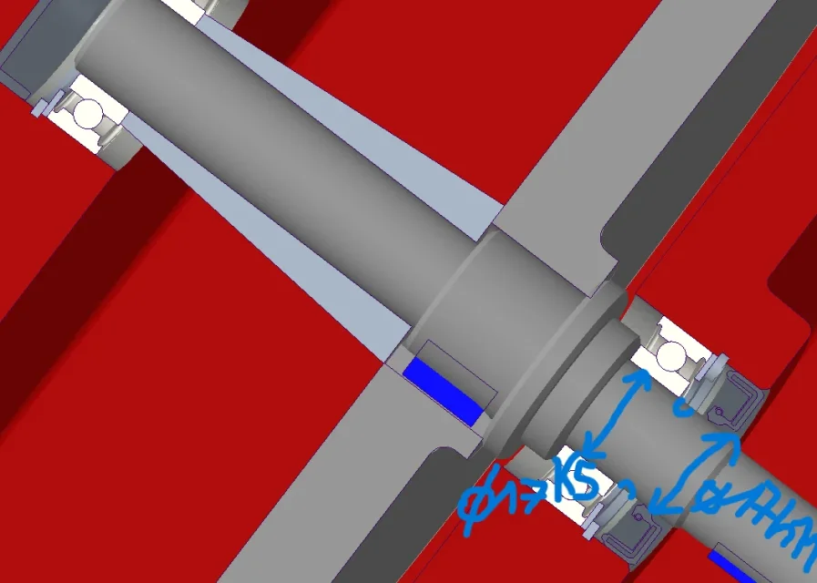
on shaft led side exit, seal and bearing are on the same section of the shaft... the bearing needs tolerance k5 while the gasket h11, is it okay to maintain that of the bearing or do a drain throat to have the two separate tolerances?
I'm sorry, I'm not very clear about how to proceed.ra1.6 I would say that it is more than good for the envelope parcel tree input.
for the k5 h11 is normally a diameter only with a perpendicular line that indicates the two pieces. at a practical level a throat, i.e. a discharge for rectification, allows to get to do one and the other correctly.
you either just do the vertical line or you better still do a throat between the two diameters.I'm sorry, I'm not very clear about how to proceed.
I create an exhaust throat where I indicated with the half-arms or just a vertical line at the table in the same position?
Okay, I'll remove my throat and I'll put everything on the table.in standard industrial gearboxes no separation throat is performed between the diameter of the bearing seat and the diameter where the seal ring lip acts (of course when it is the same nominal diameter); generally use j6 for bearing seat and f7 for holding lip; f7 tolerance facilitates the introduction of the inner ring of the bearing. for the indication on the drawing it is sufficient to report a line of separation between the two diameters (more precisely tolerances) and to quote with reference to the tree line.
it would be good to make a diameter downloaded. to facilitate the entrance.on the shaft duct, where I place the spacer that does as a bearing for bearing and wheel, extending the bearing tolerance across the tree tract and I follow a tolerance for the spacer hole (if yes, what do I agree with it?) or divide as for the seal tract?
so I keep d17 on all length, 3mm before the saddle with a vertical line and give useful tolerance for the bearing, while for the remaining length tolerance check 0, +0,6?Since you have foreseen a unique diameter of the shaft, you should predict a value that takes into account the rectification overmetal (0.3 mm on the radius) and rectifies only the final tract corresponding to the inner radius of the bearing plus 1 or 2 mm for safety.
the spacer hole will provide 0.4-0.5 mm more(in diameter) than the diameter with overmetal.
search the forum by typing: geometric tolerances; you will find discussions with various application examples.do you know which site/pdf where I can study geometric tolerances in the practical field? I know symbols and definitions but not having experience I don't know what are useful to pieces, with what values etc.
perfect thanks, because I saw that skf and schaeffler use two different approaches. . .you can take stock also from this design (post 15) of an intermediate pinion of a reducer, assimilar in part to your exit tree: Moreover, if you type in the network: Shared drawing reducing tree, in images you will find other applications.